Announcements
Imaging
The properties of NIRI in imaging mode are summarized in the following sections. Three selectable fields of view and pixel scales are available. With adaptive optics NIRI is available at f/32 for J-L' imaging (but see caveats for L'), and at f/14 for imaging out to 2.5 microns due to the increased thermal background. Imaging at L' is impossible at f/6 and only sometimes possible at f/14. The narrow band L filters (e.g., the PAH filter, Br alpha) can be observed at f/32, f/14, and f/6. M' imaging is only possible at f/32.
NIRI occasionally suffers from vertical striping and shifts in DC levels which can both vary from quadrant to quadrant. Details can be found here.
First Frame Issue: When starting exposures after changing the detector configuration (well-depth, read mode, exposure time, etc) the background or dark current level is different. Thus The first exposure of every new sequence will show poor background subtraction and should be rejected (see the detector array section for more detail). We recommend sequences include an extra step (either at the beginning, or repeat the first position at the end, or simply include N+1 different offsets). Short exposures that are not background limited (e.g., standard star measurements) are usually fine without an extra exposure. These bad first images ARE included in the distributed data, so care should be taken to review and reject them from all sequences (science, flats and darks) as necessary.
- Pixel scales and Field of View
- Field Orientation
- Imaging filters
- Exposure times
- Zero points
- Observing Strategies
- Detector array
Pixel Scales1 and Field of View2
| Camera | Pixel dimension (arc sec) | Field of View (arc sec) |
| f/6 | 0.1171 | 119.9 x 119.9 |
| f/14 | 0.0499 | 51.1 x 51.1 |
| f/32 | 0.0219 | 22.4 x 22.4 |
| f/32 + Altair Field Lens | 0.0214 | 21.9 x 21.9 |
|
1NIRI with Altair has been measured to have radial barrel distortion at f/32. This is most prominent for programs performing large offsets. The formula for removing the distortion is r' = r + k*r*r, where k = (1.32 ± 0.02) * 10^-5 . r is the uncorrected distance from the field center in pixels and r' is the corrected distance from the center in pixels. Thus, at a distance of 500 pixels from center, an object will appear about k*500*500 = 3 pixels closer to the center of the array than reality. This correction is available in an IDL program, and PIs interested in high-precision astrometry are encouraged to contact either the NIRI or Altair instrument scientists to discuss this issue. Note: This solution is valid for data taken with f/32 before August 2018. A new solution is being developed after the f/32 mirror shift. 2For full (1024 x 1024) array |
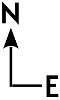
Field Orientation
The NIRI field orientation is determined by which telescope port (bottom or side) NIRI is installed on, and if on the bottom port, whether or not Altair is used. For most cases, at a PA = 0, North is up and East is to the left, however, when installed on the bottom port and used without Altair, East is to the right:
| Port | Altair | Non-AO |
| Bottom (1) |  |
 |
| Side (3 or 5) | |
|
A zero point is defined as the magnitude of an object that would yield 1 ADU/sec at an airmass of 1. They depend on instrument and telescope transmittances as well as detector electronics. Zero points tend to be stable at the 3% level over many months. Measured values need to be corrected for variation of atmospheric extinction with airmass. The following table contains zero points for NIRI with its f/6 camera and broad band filters. Extinction values are taken from Tokunaga, Simons & Vacca (2002 PASP 114, 180) for 2mm of precipitable water vapor. See their Table 2 for extinction values for other amounts of precipitable water.
NIRI Zero points
For more detailed information on the NIRI zero points please see the Instrument Performance Monitoring project web page.
| Filter | Central wavelength (µm) |
Zero point magnitude (for 1 ADU/s) |
Sky background (mag/arcsec) |
Typical extinction (mag/airmass) |
| Y | 1.02 | 22.98 | ||
| J | 1.25 | 23.97 | 15 to 16 | 0.015 |
| H | 1.64 | 24.04 | 14 to 14.5 | 0.015 |
| Kprime | 2.12 | 23.68 | 13.7 to 14.2 | 0.059 |
| Kshort | 2.15 | 23.40 | 13.6 to 14.1 | 0.043 |
| K | 2.20 | 23.43 | 13.5 to 14.0 | 0.033 |
| L' | 3.77 | 22.21 | 3.5 | 0.104 |
| M' | 4.68 | 20.1 | 0.3 | 0.223 |
Spectroscopy
Spectroscopy capability for NIRI has been decommissioned. The NIRI spectroscopy pages are provided for archival data reduction.
Low-moderate resolution spectroscopy could be obtained either at f/6 through each of the 1-5μm windows or at f/32 (the latter usually with adaptive optics) at JHK only. A variety of slit widths were available. The f/6 and f/32 pixel scales in spectroscopy mode were the same as those in imaging mode.
NIRI Sensitivity Tables
Without AO
The values in these tables are based on results from the NIRI Integration Time Calculator. They assume 70-percentile (IQ70, ~average) image quality for all categories, photometric conditions (CC50), and an airmass of less than 1.2 for the sensitivites presented here. At 3 to 5 microns median water vapor (WV50) and shorter wavelengths "any" water vapor were assumed; water vapor has little impact on the near-IR imaging sensitivity, or on spectroscopic sensitivity in the middles of the J, H, and K windows, but does significantly effect the edges of the JHK windows where absorption by telluric water vapor is strong. The estimates also use the measured telescope, camera, and detector performances. Note that some sky conditions vary outside of those stated above. For example, OH emission, although scaled by airmass, can intrinsically vary by over a factor of two from night to night and over much shorter timescales - which can alter S/N and sensitivity by +/- sqrt2 in the J, H, and K bands. Thus observers should use both the table and the ITC with some caution and conservatism.
Regarding readout noise and detector well depth, note that:
- 1-2.5um narrow band faint source imaging and spectroscopy used the shallow well and low read noise mode
- JHKsK'K imaging used the shallow well and medium read noise mode
- All thermal IR (3-5um) imaging and spectroscopy used the deep well and high read noise mode
| NIRI IMAGING SENSITIVITY (S/N=5 IN 1 HOUR, N.I. OVERHEADS) - NO ADAPTIVE OPTICS | |||||||||||||||||||||||||||
| Filter | Center wavelength (µm) | Point Sources | Extended Sources | Individual Exposure (sec) | Approx. Total Throughput | ||||||||||||||||||||||
| (mag) | (mJy) | (mag/arcsec2) | (mJy/arcsec2) | ||||||||||||||||||||||||
| J | 1.25 | 23.5 | 7E-04 | 23.6 | 6E-04 | 600 | 29% | ||||||||||||||||||||
| Jcont | 1.207 | 22.2 | 2.2E-03 | 22.5 | 2.0E-03 | 600 | |||||||||||||||||||||
| H | 1.65 | 22.5 | 1.1-03 | 22.6 | 1.0E-03 | 60 | 37% | ||||||||||||||||||||
| [FeII] | 1.644 | 21.1 | 4E-03 | 21.2 | 3.5E-03 | 600 | |||||||||||||||||||||
| K | 2.20 | 22.6 | 0.6E-03 | 22.7 | 0.6E-04 | 120 | 43% | ||||||||||||||||||||
| H2 1-0 S(1) | 2.122 | 21.5 | 1.7E-03 | 21.6 | 1.5-03 | 600 | |||||||||||||||||||||
| L' | 3.76 | 17.0 | 3.7E-02 | 17.1 | 3.3E-02 | 2.0 | 28 | ||||||||||||||||||||
| M' | 4.68 | 14.4 | 2.9E-01 | 14.3 | 2.6E-01 | 2.0 | 23% | ||||||||||||||||||||
For a figure showing the zero point in J as a function of time, please go to the page about Airglow at Maunakea (will open a new page from the GMOS instrument.)
- The estimates in the table are for exposures that are background-limited in all cases. As a result, in imaging mode there is very little difference in achieved sensitivities between the different cameras. The f/6 camera provides the best sampling and field-of-view for tip-tilt corrected images without adaptive optics correction. Because of the high and varying (with weather and airmass) background levels in the thermal IR , observations at L band and M band use the f/32 camera to prevent saturating on the sky background.
- For imaging, the ITC calculates the S/N in an aperture that maximizes S/N, given the predicted image quality for the observing conditions and wavelength requested. The sensitivity values in the table below use this optimum ITC aperture. For accurate photometry much larger apertures usually must be used, and sensitivities are reduced, typically by a factor of 2 or more.
- Approximate total throughput values in the imaging table are as measured for the entire system, including the telescope, instrument, and detector.
With AO (NGS and LGS)
Notes
- The sensitivity tables assume photometric conditions (50%-ile cloud cover), grey time (80%-ile sky background) and an airmass of less than 1.2. Note however that the OH sky emission can vary by a factor of ~2 up or down during the night
- Individual exposure times of 600s were assumed for all cases.
- Observations are assumed to be at f/32 and dithered (target object in the field at all times); sky subtraction noise is included.
- The ITC calculates the S/N in an aperture that maximizes S/N given the predicted image quality for the observing conditions and the requested wavelength.
| NIRI + ALTAIR (Natural Guide Star, Field Lens)~~~~~~S/N=5 IN ONE HOUR (N.I. OVERHEADS) | |||||
| Filter | Image Quality %-ile Bin |
Guide Star R-band (mag) |
Guide Star Distance (arcsec) |
Point Source Sensitivity (mag) |
Strehl Ratio |
| J | 20%-ile | 12 | 0 | 24.8 | 0.199 |
| 12 | 5 | 23.9 | 0.115 | ||
| 70%-ile | 12 | 5 | 23.5 | 0.015 | |
| 15 | 5 | 21.9 | 0.001 | ||
| H | 20%-ile | 12 | 5 | 22.9 | 0.318 |
| 70%-ile | 12 | 5 | 22.4 | 0.102 | |
| 15 | 5 | 21.7 | 0.019 | ||
| K' | 20%-ile | 12 | 5 | 23.2 | 0.533 |
| 70%-ile | 12 | 5 | 22.7 | 0.275 | |
| 15 | 22.4 | 0.126 | |||
| 15 | 5 | 22.2 | 0.040 | ||
| 15 | 22.1 | 0.035 | |||
| 85%-ile | 12 | 5 | 22.0 | 0.120 | |
| H2 1-0 S(1) | 70%-ile | 12 | 5 | 21.8 | 0.238 |
| NIRI + ALTAIR (Laser Guide Star, Field Lens)~~~~~~S/N=5 IN ONE HOUR (N.I. OVERHEADS) | |||
| Filter | Image Quality %-ile Bin |
Point Source Sensitivity (mag) |
Strehl Ratio |
| J | 20%-ile | 24.0 | 0.111 |
| 70%-ile | 23.1 | 0.043 | |
| 85%-ile | 22.2 | 0.014 | |
| H | 20%-ile | 23.5 | 0.187 |
| 70%-ile | 22.8 | 0.087 | |
| 85%-ile | 22.0 | 0.036 | |
| K' | 20%-ile | 23.9 | 0.294 |
| 70%-ile | 23.3 | 0.161 | |
| 85%-ile | 22.6 | 0.081 | |
| H2 1-0 S(1 | 20%-ile | 22.1 | 0.298 |
| 70%-ile | 21.5 | 0.164 | |
| 85%-ile | 20.8 | 0.083 | |
Guiding Options
Natural Seeing (Non-Adaptive Optics) Guided Observations:
NIRI standalone (i.e., without AO) requires the use of a peripheral wavefront sensor for both imaging and spectroscopy. PWFS2 is preferred over PWFS1, as it can be used on fainter guide stars, can run at a higher frequency for a given guide star, works better under windy and cloudy conditions, and is smaller and thus vignettes less of the field of view.
Laser Guide Star (LGS) and Natural Guide Star (NGS) Adaptive Optics (AO) Guided Observations:
With Adaptive Optics: ALTAIR is used as the primary guider, providing adaptive optics correction for seeing effects. ALTAIR provides both Natural Guide Source (NGS) and Laser Guide Source (LGS) capabilities with NIRI.
NGS: The guide star (which may be the target itself) is used to provide wavefront information for the deformable mirror as well as overall image motion for tip/tilt. More information can be found here.
LGS: The laser created guide star provides information for the deformable mirror while a nearby star must be used for tip/tilt. This star can be much fainter than an NGS star used with the deformable mirror. Further details can be found here.
LGS+P1: The laser created guide star provides information for the deformable mirror while in place of using a nearby star for tip-tilt focus, the peripheral wavefront sensor (PWFS1 or P1) is guided on a star that provides the tip/tilt corrections. This mode does not provide diffraction-limited resolution, but instead gives “super-seeing” by reducing the natural seeing PSF FWHM by a factor of 2-3. The major benefit of this seeing-improver mode is that it increases the LGS sky coverage to almost 100%, providing a significant level of PSF correction for a wide variety of applications. Further details can be found here.
Guidelines for Selecting Guide Stars for Your NIRI Observations:
Guidelines for selecting good guide stars are summarized in the table below. Note that the guide star brightness limits are for cloudless nights (50% CC) and optimal seeing (IQ ≤ 70%). ALTAIR can guide on fainter stars (to R~15 mag for A0 stars), but this will result in poor correction, and thus not recommended if brighter stars are available. We note that the automatic guide star selection in the Observing Tool (OT) will pick a guide star whenever possible that satisfies the criteria below.
| Guide Probe | Separation from center of NIRI FOV (field-of-view) | Guide star brightness |
| ALTAIR (NGS) | < 25" (1) |
R <~12 mag (optimal) R <~15 mag (faint limit) |
| ALTAIR (LGS) | < 25" (1) |
R <~17.5 mag (bright time) R <~18.5 mag (dark time) |
| LGS+PWFS1 | 4.75' to 7' for f/14 and f/32 | R <~ 14 mag |
| PWFS2 |
5' to 7' for f/6 4.25' to 7' f/14 and f/32(2)
|
R <~ 15 mag |
(1) The precise position of the Altair patrol field is correctly displayed with the Altair overlay in the Observing Tool (OT) position editor.
(2) For guide stars closer than 5' the position editor in the Observing Tool (OT) position editor should be inspected carefully to check that the PWFS probe does not block the science field