Announcements
Echelle Spectrograph:
The core component of MAROON-X is a modified version of the KiwiSpec R4-100 spectrograph by KiwiStar Optics of New Zealand. The instrument was designed to deliver a resolving power of R~80,000 for a 100um wide pseudo-slit at f/10 with 3.5 pixel sampling across a wavelength range of 500-920nm spread over two camera arms. A Zemax layout of the spectrograph is shown in the figure below.

Figure C1. Zemax rendition of the optical elements of MAROON-X and raytracing. The insert to the upper left shows the telecentric input relay optics which convert the f/5 fiber output (50um wide to the left in the insert) to the f/10 input accepted by the spectrograph (100um slit width).
The main disperser is a Richardson Gratings R4 echelle with a nominal blaze of 76 and a line frequency of 31.6 g/mm. Our echelle was replicated from master MR263 on a 116mm x 420mm Zerodur substrate with a 102mm x 408mm ruled area and coated with protected silver. Measurements at Richards Gratings show peak efficiencies of up to 85% at blaze. The blaze angle is 75.3±0.3deg, slightly lower than specified.
The collimator mirror, pupil transfer mirror, and both fold mirrors are made from Zerodur class 1 and coated with protected enhanced silver. A dichroic beam splitter separates the dispersed light into the two camera arms. The crossover wavelength is 660 nm. Two VPH cross-disperser grisms and camera arms cover 500-678nm, order 122-91 (useful range: 500-663nm, order 122-93) and 654-920nm, order 93-67, respectively. Both cameras have a focal length of f= 174mm and hence a moderate f/5.22.
The main spectrograph optics, including echelle grating, primary and secondary collimators, as well as the input relay and the dichroic beamsplitter are mounted on a stainless steel bench and held inside a vacuum chamber at < E-5 mbar. Cross-disperser and camera optics as well as the detectors are mounted outside of the vacuum chamber on a large optical table. The complete spectrograph, including the etalon calibrator (see Image below) is housed in an environmental chamber that is kept at 10C within 10-20mK.
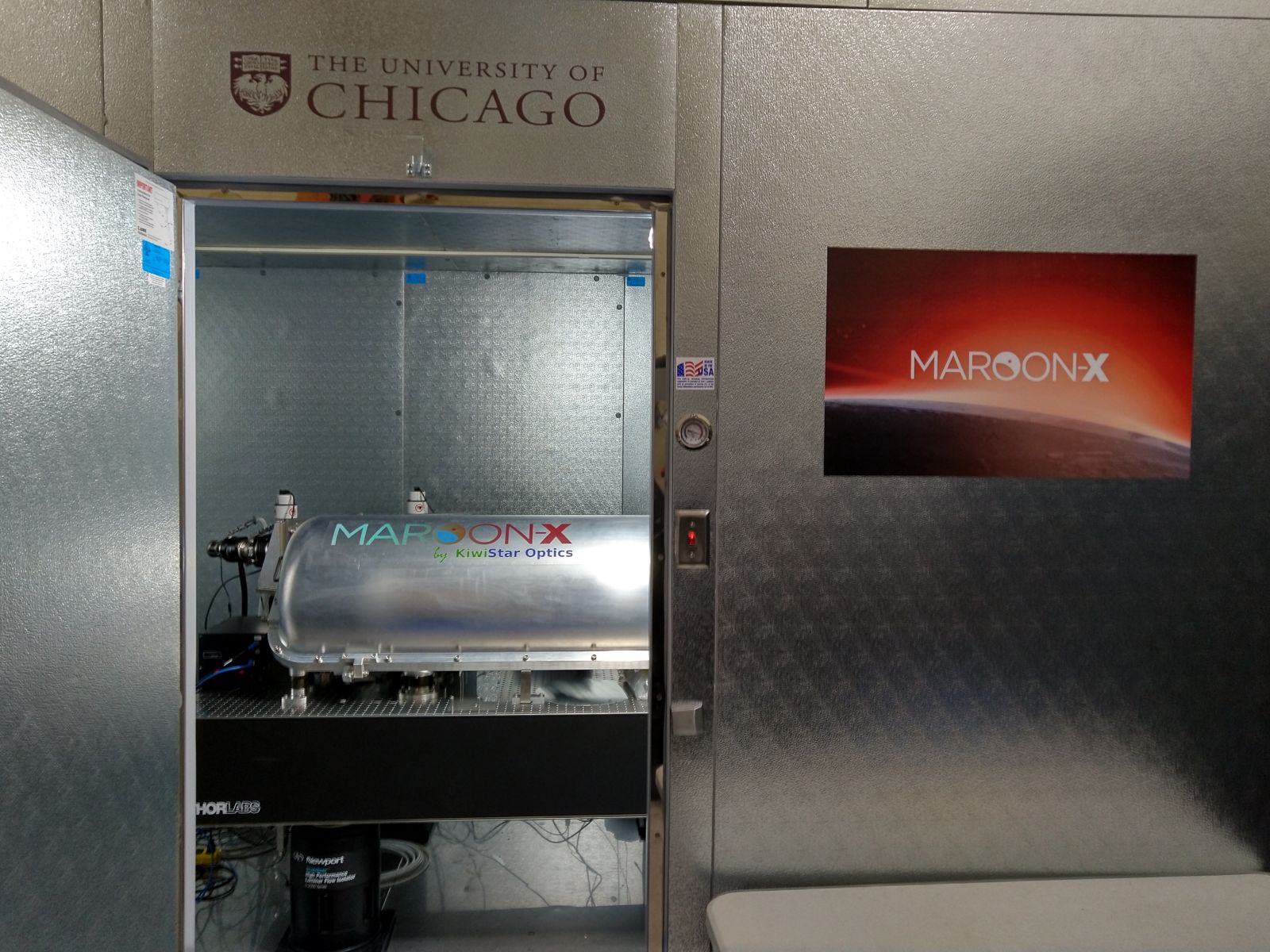
Figure C2. MAROON-X vacuum chamber with the main components of the echelle spectrograph on the optical table inside the environmental enclosure.
CCD Detectors
Each cross-disperser and camera arm is equipped with a STA4850 CCD. Both have a 4080 x 4080 format and 15um pixel size and BBAR coatings optimized for their respective wavelength coverage. STA’s Archon CCD controllers are used for both chips. Currently, only one readout mode (100kHz) and 1x1 binning is offered. Detailed characteristics are given in the table below.
| Characteristic | Blue arm | Red arm |
|---|---|---|
| CCD type | 30 micron thick epitaxial Si | 100 micron thick deep depletion |
| QE | >90% from 480-720nm |
>90% from 640-870nm >80% from 870-900nm |
| Read noise (rms@100 kHz) | < 2.9 e- | < 3.5 e- |
| sCTI/pCTI (as 1-CTE) | < 6.4E-7 / < -6.7E-8 | < 7.4E-7 / < 7.1E-9 |
| Dark current (@ -100 degC) | 2.2 e-/pix/h | 3.8 e-/pix/h |
| Full well capacity (at linearity limit) | 150 ke- (55k DN) | 153 ke- (56 kDN) |
| Full range non-linearity | 0.7 % | 0.8 % |
| Inverse gain | 2.72 e-/DN | 2.74 e-/DN |
| Amplifiers | 4 | 2 |
| Readout time (including 300pix overscan in each direction) | 54 sec | 100 sec |
Fiber Feed and Pupil Slicer:
Light arrives at the spectrograph in two 100um (0.77") octagonal fibers at f/3.33. One fiber carries the stellar light, the other the sky background. The spectrograph’s relay optics accept a 50um wide slit at f/5. The slit is made of rectangular fibers, each 50x150um. The sky fiber is directly butted to one of the rectangular fibers, causing 50% slit losses. The light of the object fiber is sliced into 3 sections and projected onto three of the rectangular fibers (see section in Spectroscopy). We opted to do the slicing in pupil space. Using micro lenses, a small image of the telescope pupil is formed, sliced and then re-imaged onto the rectangular fibers. This setup also provides additional scrambling as fiber near- and far fields are exchanged. A fifth rectangular fiber can be used as a simultaneous reference fiber. The rectangular fibers are routed into the vacuum chamber to form a physical slit. A telecentric relay optic converts the f/5 to an f/10 beam, re-imaging the 50um wide physical slit to a 100um wide pseudo slit. At the location of the pseudo slit, a physical slit mask is cutting off any light from in the fiber cladding, both in dispersion direction and at the upper and lower end of the slit.

Figure C3. Small cutout from a typical MAROON-X spectrum recorded with the blue arm (around 540nm) to illustrate how the five rectangular fibers are stacked to form a pseudo slit.
Telescope Frontend:
MAROON-X has a frontend unit that converts the f/16 beam from the telescope to an f/3.3 beam to feed the 100um (0.77") octagonal object fiber. Primary (i.e. telescope guiding) is using the PWFS2 of Gemini. The frontend unit is mounted on the bottom port of the ISS, a port shared with NIFS and NIRI.
In the frontend unit, the light passes through an atmospheric dispersion compensator (ADC) and a tip-tilt mirror provides flexure compensation between the telescope and the fiber face to provide < 0.1” average centroid stability. To achieve this, ~1% of the light that is sent towards the fiber is picked up by a beam splitter and imaged by a fast and sensitive acquisition and guide camera (sCMOS with >90% peak QE, 400-950nm passband). Three back-illuminated single-mode fibers surrounding the object fiber allow to track the apparent position of the science fiber during the integration. A slow (f<1Hz) guide loop is steering the tip-tilt mirror to keep the centroid of the star on the measured fiber position. Exposure times as short as 0.05s can be chosen. ND Filters allow a further reduction of the flux for bright stars. Exposure times of up to 30 sec allow guiding on targets as faint as ~16mag.
A second 100um (0.77") octagonal fiber 20” from the object fiber is used to record the sky background.
The frontend also facilitates the illumination of the object and sky fibers with calibration light. Calibration light (flatfield, ThAr, etalon) is sent up from the spectrograph via an additional fiber integrated into the fiber bundle. The tip-tilt mirror is used to steer the light onto the object or the sky fiber.
An optical layout of the frontend unit is shown in the figure below.

FIgure C4. Optical design for the frontend unit. The f/16 focus of Gemini is reimaged onto a f/3.3 image plane, matching the acceptance cone of the fiber. A custom beamsplitter (BS) cube reflects 1% of the light, which is re-imaged with a second camera onto a sCMOS detector for active guiding. A tip-tilt mirror in the pupil plane facilitates the guiding with a precision of <0.1”. A classical ADC system provides on-axis compensation of the atmospheric dispersion to under 0.05” over 500-920nm down to air mass 2. Retractable optics in front of the ADC (not shown here) are used to re-image the calibration fiber onto the science and sky fibers.
Calibration System:
MAROON-X has its own calibration system and is not using GCAL. All light sources are fiber coupled and fiber switchers are used to select the light source for the calibration fiber leading up to the frontend (for calibration of the object and science fiber) and for the simultaneous calibration fiber.
Light sources include a Tungsten-Halogen lamp for flatfielding and a Photron ThAr arc lamp for wavelength calibration. For precision RV measurements, the ThAr lamp alone is not adequate.
MAROON-X is using a stabilized Fabry-Perot etalon illuminated by a white light fiber laser providing a dense comb of emission lines with a spacing of 15 GHz and an unresolved line-width of 340 MHz. This translates to a line spacing of 2 - 3.6 resolution elements and a line-width of 1/20 to 1/10 of a resolution element between 500 and 920nm, respectively.
ThAr exposures are used to supplement the etalon exposures and to provide both absolute wavelength zeropoints and a solution for the etalon dispersion. The etalon optics are inside a separate vacuum vessel in the temperature stabilized environmental enclosure.