Announcements
Detector Array Properties
The properties of the Aladdin III InSb detector array for the GNIRS science channel are given in Table 1 below.
The array has nicely uniform response, only a few regions of bad and dead pixels (see table below) very low dark current and low read noise in the lowest background mode. The bias voltage may be adjusted to increase the well depth for thermal IR (L and M band) observations or for very bright targets. InSb detectors have nearly 100 percent internal quantum efficiency (QE) from 0.4 to 5 microns, with a rolloff near the cutoff wavelength of 5.5 microns. The surface of the material is highly reflective (36 percent), but this is reduced by an anti-reflection coating that gives the array an effective QE of ~90 percent over the 0.9-5 micron interval.
| Table 1: Detector Characteristics | |
| Array | Aladdin III InSb (Hughes SBRC) |
| Pixel format | 1024x1022 27-micron pixels |
| Spectral Response | <0.9 to 5.5 microns |
| Dark Current | 0.15 e-/s/pix |
| Gain | 13.5 e-/ADU |
| Well depth, 0.3V bias (near-IR) |
90,000 e- (7,000 ADU) non-linear response above 5,000 ADU |
| Well depth, 0.6V bias (thermal-IR) |
180,000 e- (14,000 ADU) non-linear response above 10,000 ADU |
| Quantum efficiency | about 90% |
| Difference in odd/even row response | 7% |
| Flat field repeatability | TBD |
| Residual image retention | Minimal impact on science; details |
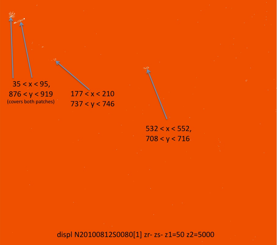
| Regions of bad pixels | (532< x <552, 708< y <716) (177< x <210, 737< y <746) (35< x <95, 876< y < 919) |
Read Modes
There is a tradeoff between the detector read noise and the time required to read out the array. The best choice depends on the brightness of the object and the background at a given wavelength (see the Observing Strategies page for more guidance).
| Table 2: Read Modes | ||||||
| Read Mode | Low Noise Reads |
Digital Averages |
Read Noise (e-) |
Min. exp time* (sec) |
Recommended min. exp time* (sec) |
Recommended Use |
| Very Bright Objects; high background |
1 | 1 | 155 | 0.2 | <1.0 | low res. M |
| Bright Objects medium background |
1 | 16 | 30 | 0.6 | ~2.0 | Exp ~1 - 20s and/or sqrt(sig+bkgnd)>80 e/pix |
| Faint Objects low background |
16 | 16 | 10 | 9.0 | 20.0 | Exp ~20 - 60 s and/or sqrt(sig+bkgnd) < 50 e/pix |
| Very Faint Objects very low background |
32 | 16 | 7 | 20.0 | 60.0 | Exp > 60 s and/or sqrt(sig+bkgnd) < 20 e/pix |
* The minimum exposure times are the times required to read the array. The recommended minimum exposure times allow efficient observing (spending at least 2/3 of the time actually exposing the array as opposed to reading it).
Some problems and features related to the detector and its controller are described on the "Known Issues" page.
Filters
Photometric Filters
The filters listed below may be used for photometry on the Mauna Kea system.
As they vignette the outer portions of the GNIRS acquisition keyhole, they should not be used for purposes of acquisition for spectroscopy.
| Mauna Kea Photometric Filters in GNIRS | |||||
| Filter Name | Wavelength range | Transmittance plot measured in GNIRSa |
Transmittance numerical data measured in GNIRSa |
Transmittance curve from manufacturer |
Gemini ID |
| Y | 0.97-1.07µm | yes | yes | - | G0544 |
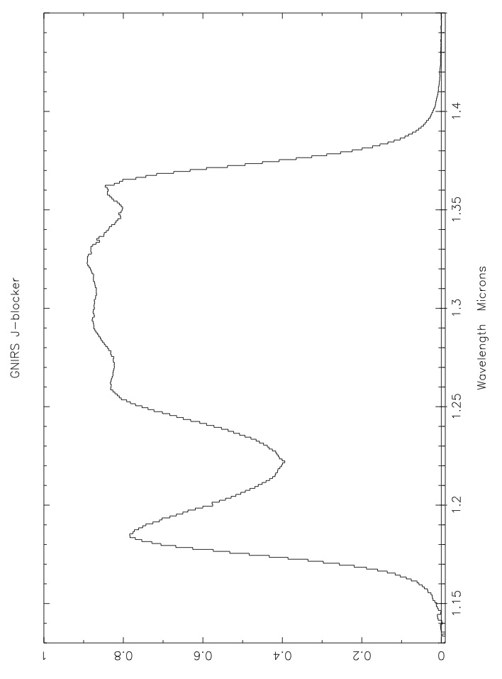
| J-MK | 1.17-1.34µm | yes | yes | - | G0545 |
| K-MK | 2.03-2.37µm | yes | yes | - | G0546 |
ascaled to transmittance of the XD filter in the relevant wavelength interval
Order-blocking Filters
The filters listed below are used during spectroscopy for order-blocking and (with the exceptions of M, L, and XD) for acquisition.
For acquisition they provide complete and unvignetted views of the acquisition "keyhole," whose dimensions are shown here.
| Order-blocking Filters for Spectroscopy and Acquisition | ||||||
| Filter Name | Diffraction order |
Wavelength range | Transmittance plot measured in GNIRSa |
Transmittance numerical data measured in GNIRSa |
Transmittance curve from manufacturer |
Gemini ID |
| Mb | 1 | 4.4 - 6.0um | - | - | yes | G0501 |
| Lb | 2 | 2.8 - 4.2um | - | - | yes | G0502 |
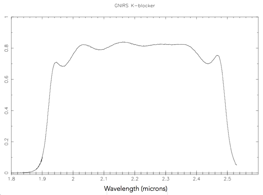
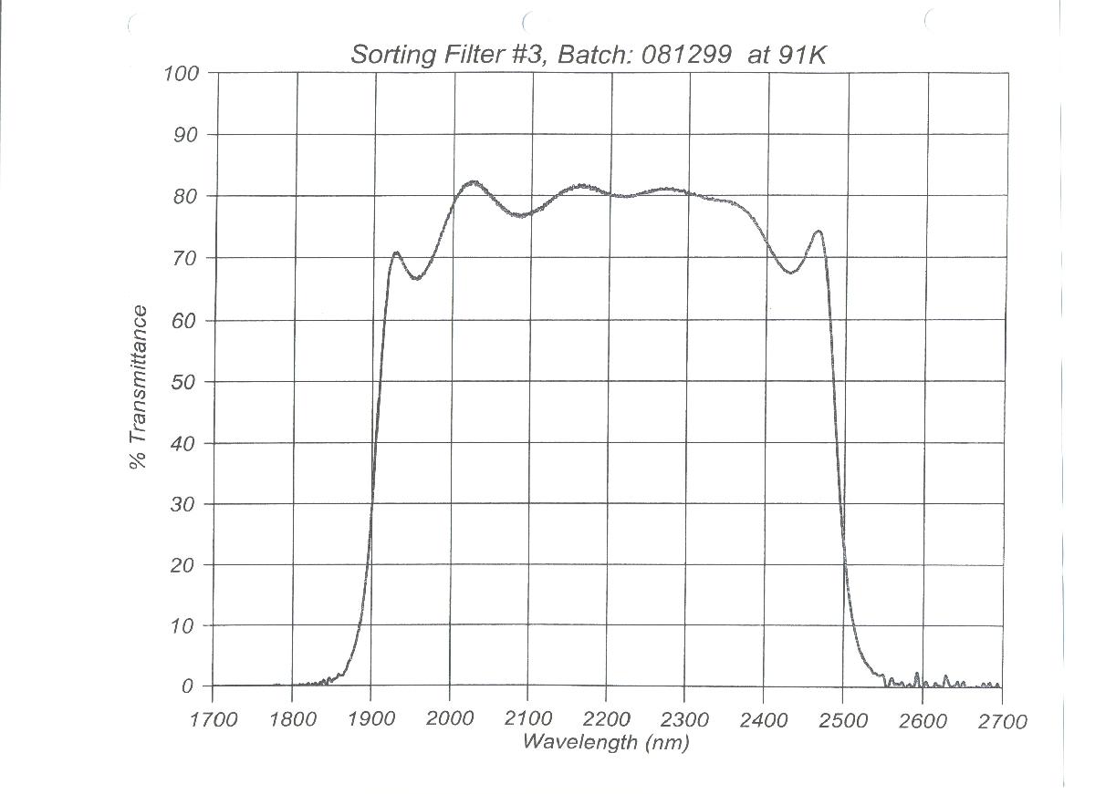
| K | 3 | 1.91 - 2.49um | yes | yes | yes | G0503 |
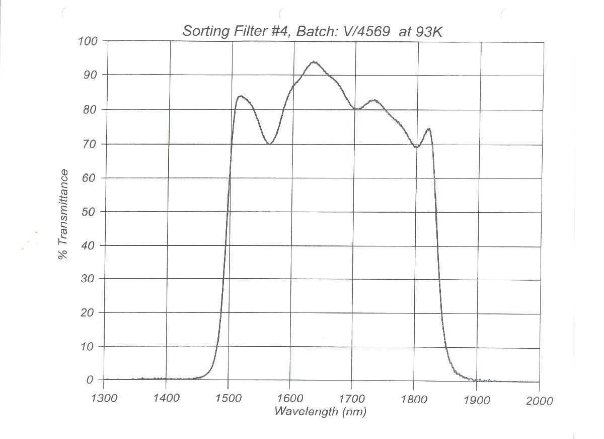
| H | 4 | 1.47 - 1.80um | yes | yes | yes | G0504 |
| J | 5 | 1.17 - 1.37um | yes | yes | yes | G0505 |
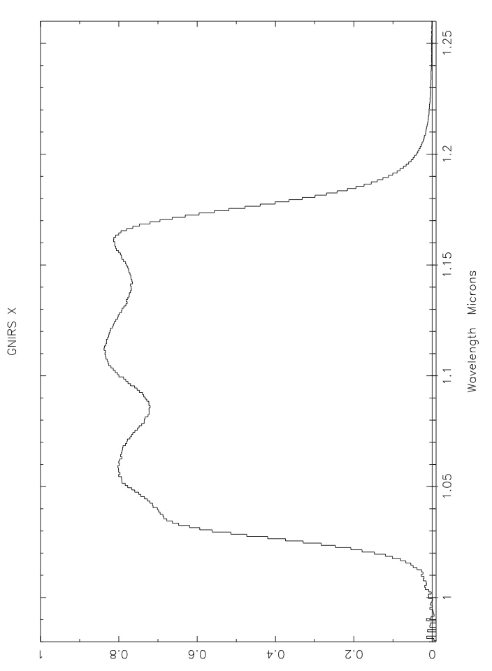
| X | 6 | 1.03 - 1.17um | yes | yes | yes | G0506 |
| XDb | 3-8 (cross-disp) | 0.9 - 2.56um | - | - | yes | ED316 |
ascaled to transmittance of the XD filter in the relevant wavelength interval
bNot used for acquisition
Acquisition Filters
Acquisition filters are defined in acquisition observation sequences - see the OT Details and Acquisition pages for more information.
| Acquisition Filters (narrow band) | ||||||
| Filter Name | Width | Central Wavelength | Transmittance plot measured in GNIRS |
Transmittance data measured in GNIRS |
Transmittance plot from manufacturer |
Gemini ID |
| H2 | 1.5% | 2.122um | yesa | yesa | - | G0521 |
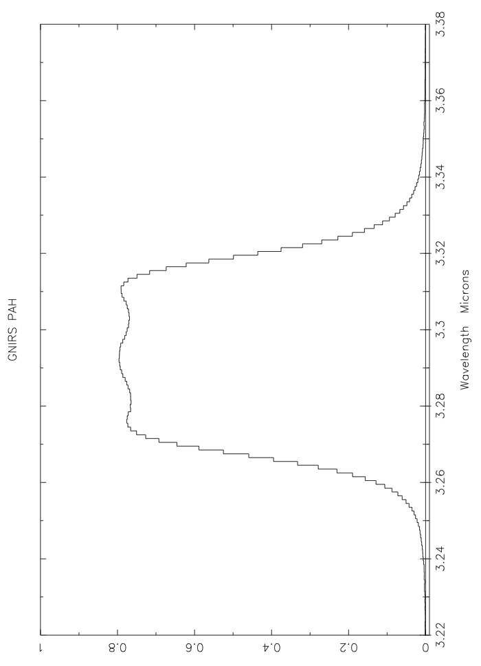
| PAH | 1.5% | 3.295um | yesb | yesb | - | G0523 |
ascaled to transmittance of the XD filter in the relevant wavelength interval
bscaled to transmittance of the L filter in the relevant wavelength interval
Neutral Density Filters
A neutral density filter used for acquisition of very bright objects is also available for use (currently with the H and H2 filters only).
Its properties are summarized below. Because the ND filter offsets images by ~0.1 arcsec perpendicular to the slit, It should not be used if the slit width is 0.45 arcsec or less, unless the neutral density is also used for spectroscopy.
| Attenuation by Neutral Density Filter | |||||
| 1.1µm | 1.25µm | 1.65µm | 2.2µm | 3.5µm | 4.8µm |
| 350X | 250X | 170X | 130X | 100X | 85X |
Slit Properties
The spectrograph entrance slit is defined by two mechanisms. The width of the slit is defined by the one of several slits in a photo-etched mask located in the slit slide; the length of the slit is defined by one of several openings in the decker slide.
The slit mask is located at the re-imaged focal plane, while the decker apertures are slightly ahead of it, and therefore somewhat out of focus (by a few pixels). The decker sizes are matched to the full width of the array in long slit mode, or to the minimum spacing between adjacent spectra when the cross-dispersing prisms are used.
Width
The slit widths currently available are listed below:
| Slit name | Slit width (pixels) [nominal values] |
|
| short camera (0.15"/pix) | long camera (0.05"/pix) | |
| 0.10 arcsec | n/a | 2 |
| 0.15 arcsec | n/a | 3 |
| 0.20 arcsec | n/a | 4 |
| 0.30 arcsec | 2 | 6 |
| 0.45 arcsec | 3 | 9 |
| 0.675 arcsec | 4.5 | 13.5 |
| 1.0 arcsec | 6.7 | 20 |
Lengths
The slit (decker) lengths in the long slit and crossed-dispersed modes are:
| Configuration | Slit length | |
| short camera | long camera | |
| Long-slit | 99 arcsec | 49 arcsec |
| Cross-dispersion | 7.0 arcseca | 5.1 arcseca or 7.0 arcsecb |
a 0.9 - 2.5 µm; see the prisms and XD page
b 1.2 - 2.5 µm; see the prisms and XD page
Throughputs
Slit throughputs for several different slit widths are presented in the following table as a function of image quality. Note that these throughputs are for an S/N-optimized software aperture (i.e. integrated along the slit) of 1.4 times the image FWHM and are not based on the total signal within the slit. The shape of the model PSF does not vary significantly across the 1-5um range and so this table is independent of wavelength. (Of course the delivered image quality does vary with wavelength and is described as part of the observing condition constraints). The values in this table were calculated with the GNIRS Integration Time Calculator.
| Slit width (arcsec) |
Image quality (50% EED in arcsec) | ||||||
| 0.33 | 0.39 | 0.50 | 0.61 | 0.81 | 0.89 | 1.56 | |
| 0.10 | 0.23 | 0.19 | 0.15 | 0.12 | 0.09 | 0.08 | 0.04 |
| 0.15 | 0.34 | 0.30 | 0.24 | 0.19 | 0.14 | 0.13 | 0.07 |
| 0.20 | 0.45 | 0.40 | 0.32 | 0.26 | 0.19 | 0.17 | 0.09 |
| 0.30 | 0.62 | 0.56 | 0.46 | 0.38 | 0.29 | 0.27 | 0.14 |
| 0.45 | 0.78 | 0.72 | 0.63 | 0.54 | 0.42 | 0.39 | 0.23 |
| 0.675 | 0.82 | 0.81 | 0.73 | 0.66 | 0.54 | 0.50 | 0.31 |
| 1.0 | 0.90 | 0.87 | 0.83 | 0.81 | 0.74 | 0.71 | 0.49 |
Orientation
Slit orientation: With GNIRS mounted on a side port of Gemini North and for a slit position angle of 90 degrees, further east corresponds to lower column numbers. For a slit position angle of 0 further north corresponds to lower column numbers.
Prisms and XD Spectroscopy
GNIRS contains two prisms designed to enable cross-dispersed spectroscopy in the 0.9-2.5 µm region. One, known as SXD, was designed for use with the short blue camera (0.15"/pix), and the other, known as LXD, for use with the long blue camera (0.05"/pix). The prisms disperse incident light in the direction orthogonal to that of the gratings, which allow grating orders 3-8 to appear at different locations on the array, as shown here. The prisms are made of SF57 glass and have excellent transmission across almost the whole wavelength range but attenuate slightly at the long wavelength end of the K-window.
Because the prisms spread the orders along the slit direction, it is necessary to use a much shorter slit than can be used in the single order / long slit mode. The slit in use with the prism for the short blue camera prism has a length of 7.0 arcsec; that for the long blue camera has a length of 5.0 arcsec. The long blue camera can also be used with the SXD prism, and the 7.0" slits, but then can only cover orders 3-5 (J, H, and K - but may miss the very shortest part of the J band). If the science does not require the shorter wavelength orders, the user can make use of this configuration which gives increased spatial coverage and greater flexibility (e.g. in nodding along the slit), with only a small degradation in spectral resolution.
Atmospheric refraction, which causes a wavelength dependent smearing of the light from the target along the elevation angle (sometimes called the parallactic angle), is always an issue at zenith angles greater than 45 degrees for the long camera and can be an issue for the short camera, particularly when the narrowest slits are used. The effect of differential refraction is shown in this table. Note that roughly 2/3 of the differential refraction in the 1.0-2.5 µm region occurs between 1.0 µm and 1.5 µm, and that the effects of flexure between the guider and GNIRS also need to be considered when selecting the position angle of the slit.
The prisms degrade the spectral resolution when used with the long blue camera at the highest spectral resolutions (i.e., with the narrowest slit - 0.10 arcsec). The degradation has been measured to be 15% with the LXD prism and 25% with the SXD prism. With wider slits the degradation is much less.
The following table summarizes the properties of each cross-dispersed mode described above.
| GNIRS in XD Mode | ||||
| Configuration camera+prism |
Slit Length (arcsec) |
orders observed | wavelength coverage |
spectral resolution with 2-pix wide slit |
| SB (0.15") + SXD | 7.0 | 3-8 | 0.9-2.5µm | 2.0 pix |
| LB(0.05") + LXD | 5.0 | 3-8 | 0.9-2.5µm | 2.3 pix |
| LB(0.05") + SXD | 7.0 | 3-5 | 1.2-2.5µm | 2.5 pix |
The GNIRS grating turret contains three gratings, each with an effective first order blaze wavelength of 6.6 µm. The wavelength diffracted with peak efficiencies then correspond fairly well to the atmospheric windows centered at 5, 3.5, 2.2, 1.65, and 1.25 µm (M, L, K, H, J) for orders 1 through 5 respectively. The blocking filters used for these orders cover most or all of the free spectral ranges of the individual orders. A filter for order 6 (1.1 µm, called X) is also available.
The coverages and resolving powers provided by the gratings are tabulated below for the short (0.15"/pix) and long (0.05"/pix) blue and red cameras. The blue cameras are used in the XJHK bands, the red cameras in the LM bands. The resolving powers (λ / Δλ) in the table are for 2-pixel wide slits. Wider slits are available, see the list of slits. Note that the wavelength coverage within an order does not depend on the central wavelength setting, and that the resolving power within an order increases with wavelength. Note also that the resolving power depends is proportional to 1/(slit width) for sources that fill the width of the slit; the values of R in the table are for the 0.3" slit with the short cameras and for the 0.10" slit with the long cameras and are the highest ones achievable.
| Grating (l/mm) |
Order - Band | Blocking Filter Range (microns) | Short camera (0.15"/pix), 0.30" slit | Long camera (0.05"/pix), 0.10" slit | ||
| Coverage (microns)(a) | Resolving power (2 pix wide slit)(b,c) |
Coverage (microns)(a) | Resolving power (2 pix wide slit)(b,c) |
|||
| 10.44 | 6 - X (1.10µm) | 1.03-1.17 | (d) | (d) | 0.332(f,g) | ~2,100 |
| 10.44 | 5 - J (1.25µm) | 1.17-1.37 | (d) | (d) | 0.398(f,g) | ~1,600 |
| 10.44 | 4 - H (1.65µm) | 1.47-1.80 | (d) | (d) | 0.497(f,g) | ~1,700 |
| 10.44 | 3 - K (2.20µm) | 1.91-2.49 | (d) | (d) | 0.663(f,g) | ~1,700 |
| 10.44 | 2 - L (3.50µm) | 2.8-4.2 | (d) | (d) | 0.995 | ~1,800 |
| 10.44 | 1 - M (4.80µm) | 4.4-6.0(i) | (d) | (d) | 1.99(e) | ~1,200 |
| 31.7 | 6 - X (1.10µm) | 1.03-1.17 | 0.331(f,g) | ~1,700(h) | 0.110(i) | ~5,100 |
| 31.7 | 5 - J (1.25µm) | 1.17-1.37 | 0.397(f,g) | ~1,600(h) | 0.132(i) | ~4,800 |
| 31.7 | 4 - H (1.65µm) | 1.49-1.80 | 0.496(f,g) | ~1,700(h) | 0.166(i) | ~5,100 |
| 31.7 | 3 - K (2.20µm) | 1.91-2.49 | 0.661(f,g) | ~1,700(h) | 0.221(i) | ~5,100 |
| 31.7 | 2 - L (3.50µm) | 2.80-4.20 | 0.992 | ~1,800 | 0.332 | ~5,400 |
| 31.7 | 1 - M (4.80µm) | 4.4-6.0(j) | 1.98(e) | ~1,240 | 0.660 | ~3,700 |
| 110.5 | 6 - X (1.10µm) | 1.03-1.17 | 0.094(i) | ~6,600 | 0.0316 | ~17,800 |
| 110.5 | 5 - J (1.25µm) | 1.17-1.37 | 0.113(i) | ~7,200 | 0.0380 | ~17,000 |
| 110.5 | 4 - H (1.65µm) | 1.49-1.80 | 0.142(i) | 5,900 | 0.0475 | ~17,800 |
| 110.5 | 3 - K (2.20µm) | 1.91-2.49 | 0.189(i) | ~5,900 | 0.0633 | ~17,800 |
| 110.5 | 2 - L (3.50µm) | 2.80-4.20 | 0.280 | ~6,400 | 0.0944 | ~19,000 |
| 110.5 | 1 - M (4.80µm) | 4.4-6.0(j) | 0.575 | ~4,300 | 0.192 | ~12,800(k) |
Notes:
(a) Important: Wavelength coverages are accurate to +/-2 percent. Wavelength is linear with array pixel number. Actual wavelength settings (specified in the OT by the central wavelength) are accurate to better than 5 percent of the wavelength coverage. E.g., if the requested setting with the 110.5 l/mm grating and short camera has a central wavelength of 3.700 µm, the nominal spectral range delivered will be 3.560 - 3.840 µm, but could be shifted by as much as 0.014 µm either way. Should an observing program require higher accuracy than the above, a note should be added at phaseII.
(b) Values are for the wavelengths in column 2. Values are linear with wavelength within an order; for example, for the 31.7 l/mm grating and the short camera R~1550 at 3.0µm and R~2050 at 4.0µm.
(c) Resolving power depends on 1/(slit width) for sources that fill the slit width; for example, the values of R for a 3 pixel-wide slit are 2/3 the values in the table.
(d) This mode potentially provides R=570 but offers no advantage over R=1700 and is not used in practice.
(e) Not recommended; the next higher resolution grating covers almost the entire accessible wavelength range in the M window and can be used with longer exposure times and significantly lower overheads.
(f) When used in single order (long slit) mode wavelength coverage is broader than bandpass of the blocking filter.
(g) When used with a cross-dispersing prism a complete 0.8-2.5µm spectrum is obtained across five orders (3-8).Efficiency in orders 7 and 8 is low.
(h) Since November 2012 and for the cross-dispersed mode with the 2 pix wide slit only resolving powers are somewhat lower, as follows: X-1400; J-1400, H-1400; K-1300. For cross-dispersion with other slit widths use the table and footnote c.
(i) When used with a cross-dispersing prism 0.1-0.2µm disjoint sections of the 0.9-2.5µm spectrum are obtained in the five orders (3-7). 3-4 wavelength settings are required to provide complete wavelength coverage
(j) Detector does not respond to light at wavelengths greater than 5.4 microns.
(k) Resolving power significantly lower than in other orders (because grating angles corresponding to M band in first order are significantly less than the angles of other bands in their orders).