Announcements
|
All of these subsystems are linked together by loops and offloads. GeMS can feed two dedicated instruments: GSAOI and Flamingos2. |
|
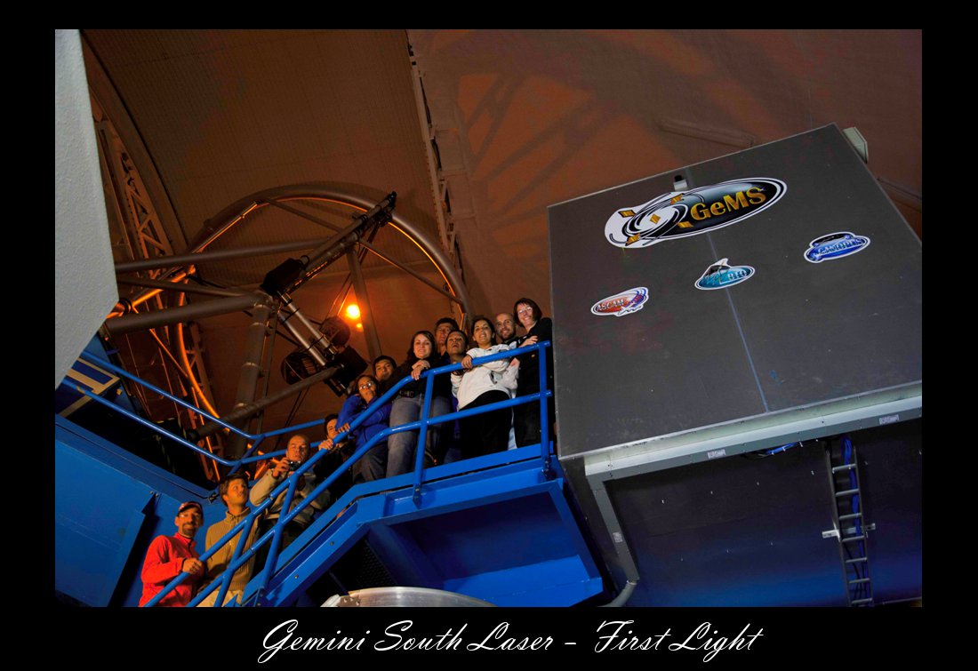
Gemini South LaserGS Laser History:The Gemini South (GS) Observatory acquired a 50W sodium Guide Star Laser System back in March 2010, as one of the key components of the Gemini Multi-Conjugate Adaptive Optics System (GeMS) project. After a successful post-delivery acceptance in the laboratory, the system was installed on the elevation platform of the telescope. March 2010: The Gemini South Telescope receives its new 50W sodium laser Following an intensive period of optimization, the Gemini South Laser Guide Star Facility (LGSF) delivered its first light on the sky in January 2011. Over the few months following the event, and while the LGSF was being commissioned, the GS laser team was able to gather considerable data concerning its laser system, and therefore ways to work on improving both its overall performance and reliability.
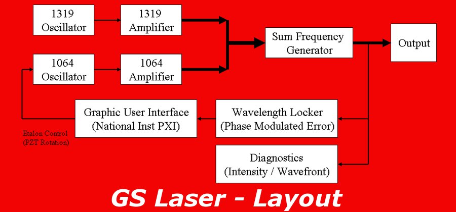
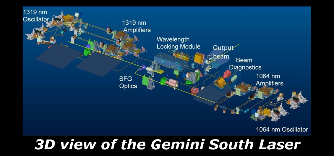
GS Laser Design:
The system architecture is based on single pass Sum Frequency Mixing (SFM) of high power outputs of two Nd:YAG MOPAs (master oscillator-power amplifier) operating at 1064 nm and 1319 nm. The 589 nm output is generated via SFM of 1064 nm and 1319 nm Nd:YAG lasers in a Lithium Triborate (LBO) nonlinear crystal.
GS Laser performance:
The table below contains the system requirements and demonstrated results. The system displays good day to day repeatability after extended 10 hour warm-up periods. However, it does require monthly alignment maintenance to compensate for beam pointing walk off. The mostly likely cause is thermal hysteresis of MO’s opto-mechanical mounts.
|

Beam Transfer OpticsThe Laser Guide Star Facility (LGSF) provides the telescope Adaptive Optics (AO) facility with a source of coherent light for the optical excitation of the mesospheric sodium layer to enable the production of an artificial beacon source or “guide star”. The LGSF subsystems are: the Laser System, Beam Transfer Optics (BTO), Laser Launch Telescope (LLT), and Safety Systems.
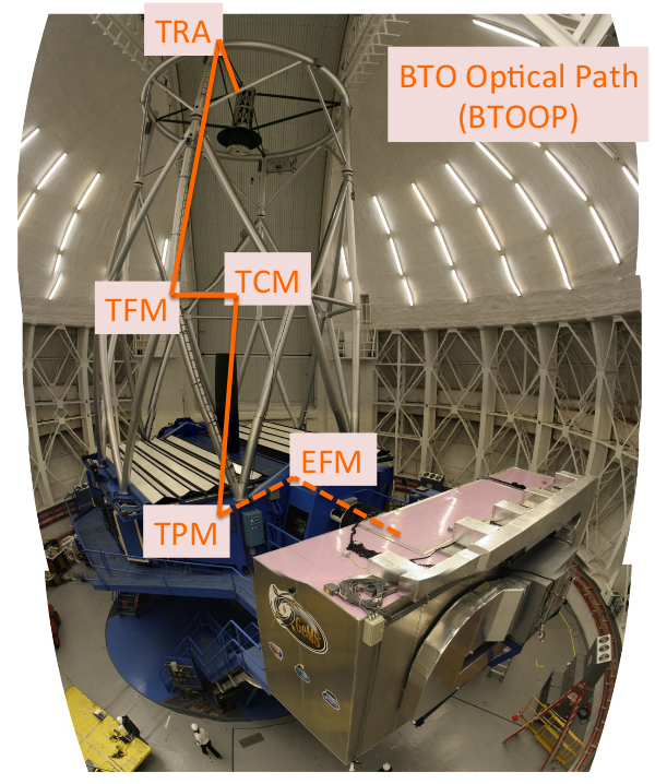
The Beam Transfer Optics (BTO) subsystem of the LGSF relays the laser beam(s) from the output of the Laser System to the input of the Laser Launch Telescope (LLT). The BTO include multiple mirrors, lenses, and beam splitters, as well as various sensors and diagnostic equipment. The part of the BTO that relays the laser beam from the Laser System to the top-end ring of the telescope is called the BTO Optical Path (BTOOP), while the part of the BTO that is located behind the LLT is called the BTO Optical Bench (BTOOB).
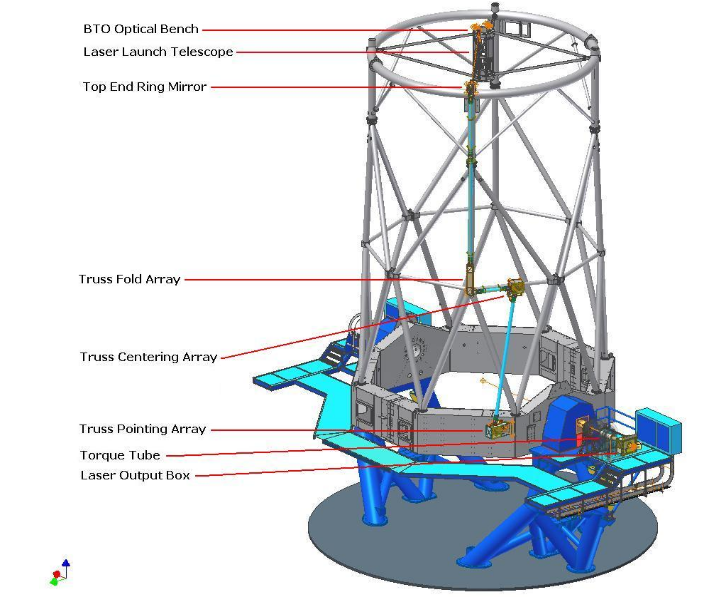
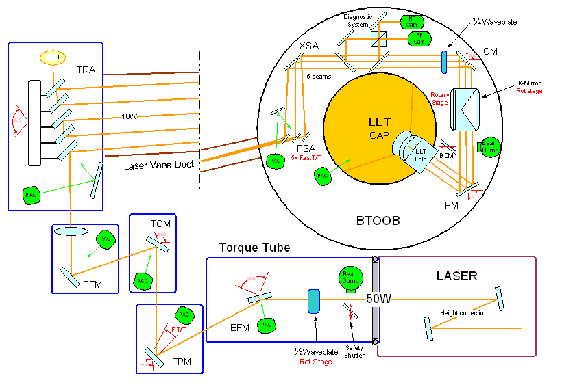
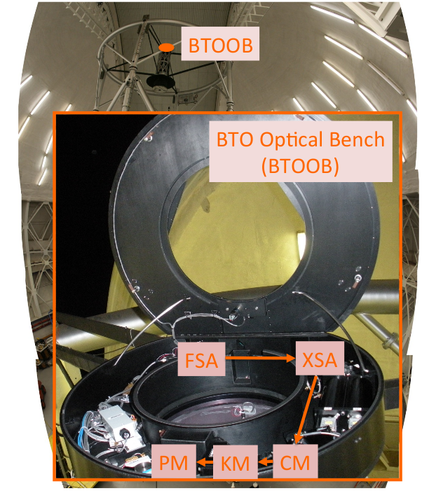
Below is a schematic view of the full BTO on the telescope, and a drawing of the optical elements of BTOOP and BTOOB:
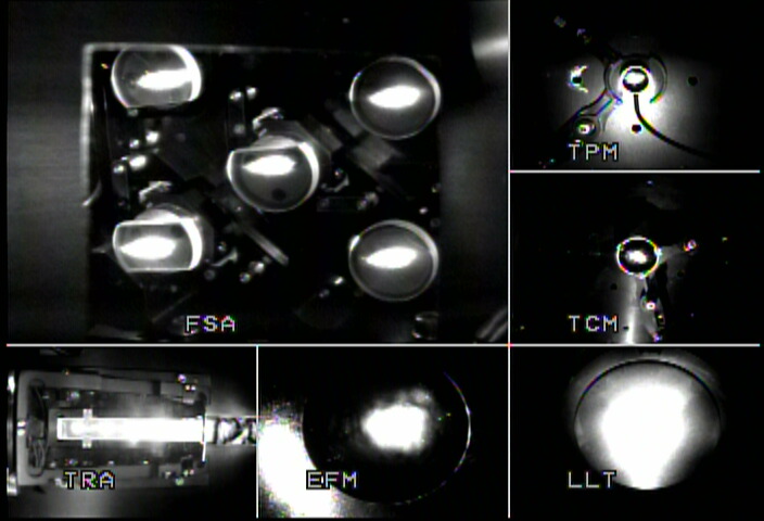
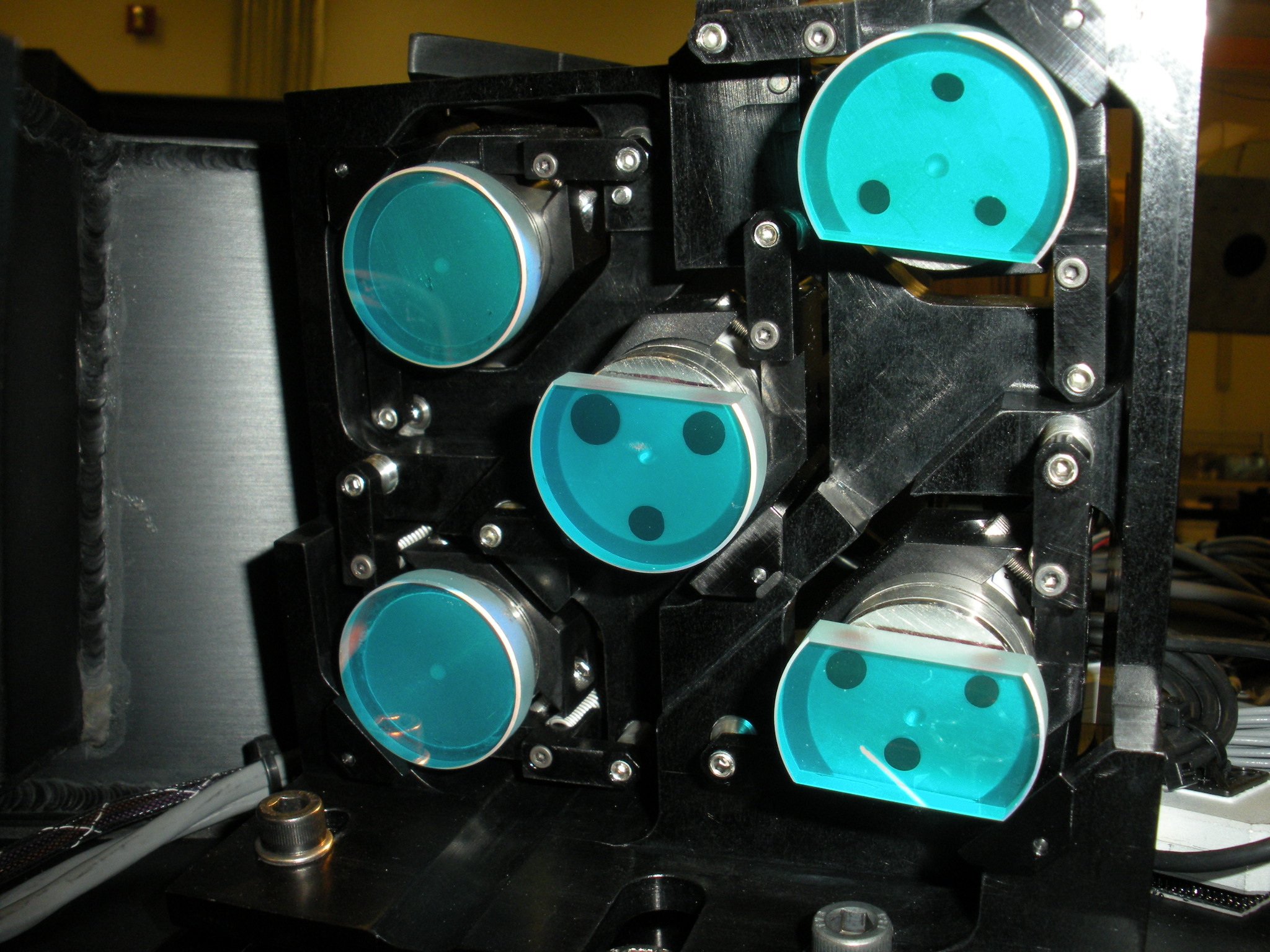
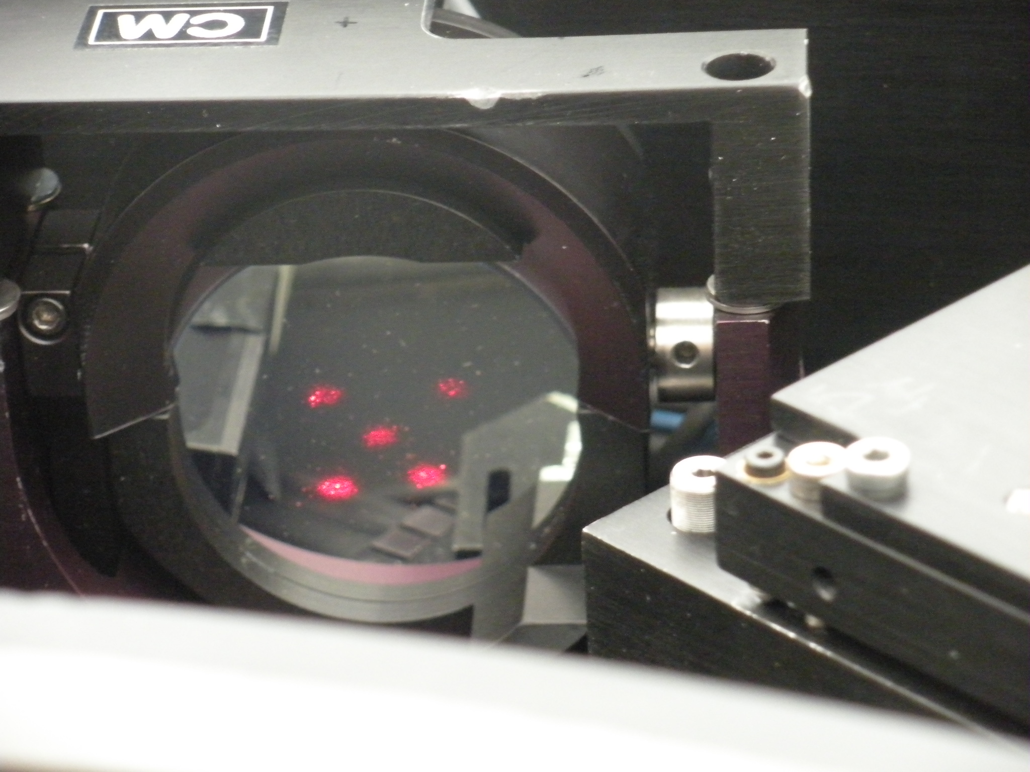
Beside relaying the laser light from the laser to the LLT, other BTO functionalities include slow and fast compensation of telescope flexures and laser beam jitter, laser beam quality monitoring, beam shuttering, and laser polarization control. Beam alignment inside the BTO can be monitored at any time using a total of six video cameras imaging the EFM, TPM, TCM, TRM, FSA and LLT primary mirror assemblies. An example of such an image is shown below:
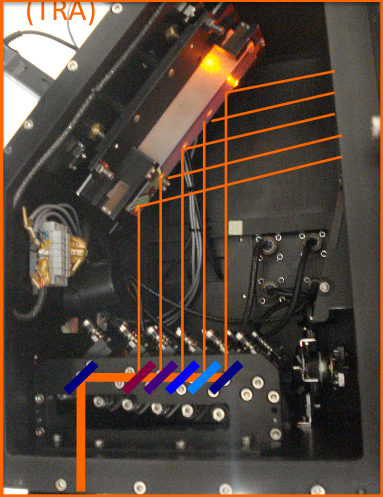
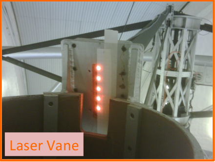
BTOOPThe laser exits the laser service enclosure as a single beam. It first travel through the “laser output box”, where the safety shutter and polarizing optics are located. Next, the beams travel through the BTO “torque tube” heading straight to the Elevation Fold Mirror (EFM) that redirects it to the Truss Pointing Mirror (TPM). TPM sends the beam up along the telescope truss to the Truss Centering Mirror (TCM) where it is redirected to the Truss Fold Mirror (TFM). After reflection on TFM the laser beam pass through three relay lenses used to image the output of the laser system onto the LLT entrance pupil. It then reaches the Top-end Ring Array (TRA), which is a combination of 4 beams splitter and a mirror, that actually divide the single 50W beam, into the 5 x 10W beams. At that points, the 5 beams are vertically aligned, and they are crossing the primary mirror of the telescope behind the spider, in a laser vane duct up to the BTO Optical Bench (BTOOB).
The combination of EFM, TPM, TCM and TRA provides open-loop compensation of the telescope flexures via an elevation-based look-up table (LUT) to maintain alignment of each laser beam relative to the narrow, 12mm-wide laser vane duct. The split of the single 50W beam into the 5 x 10W beams is done by TRA.
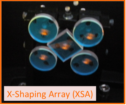
BTOOBInside the BTOOB, the five beams are received by the Fast Steering Array (FSA) which steers each of them independently to the X-Shaping Array (XSA) where the final five-star X-shaped laser constellation is formed. Finally the beams are reflected off the Centering Mirror (CM), pass through the BTOOB K-Mirror (KM), and are eventually reflected off the Pointing Mirror (PM) into the Laser Launch Telescope (LLT) for projection to the sky. A mirror can be inserted in the laser path between KM and PM so as to divert the laser light onto a power meter, thus enabling laser propagation through the entire BTO (minus PM) without projection to the sky. The entire BTO path is enclosed in tubes for safety reasons mainly, and the path is flushed with clean air to minimize dust deposition on BTO optics and prevent coating damage.
Fast Steering Array (FSA)
X Shaping Array (XSA)
Pointing and Centering Mirrors (PM & CM)The Pointing Mirror (PM) and Centering Mirror (CM) are used to (respectively) aligned the constellation on the sky, and center the beams on the LLT. While the telescope is tracking, we are using a LUT for PM/CM that keeps both the constellation and the location of the beams on the LLT well centered versus elevation and flexure. A second LUT controls the position of PM/CM vs. the K-Mirror position.
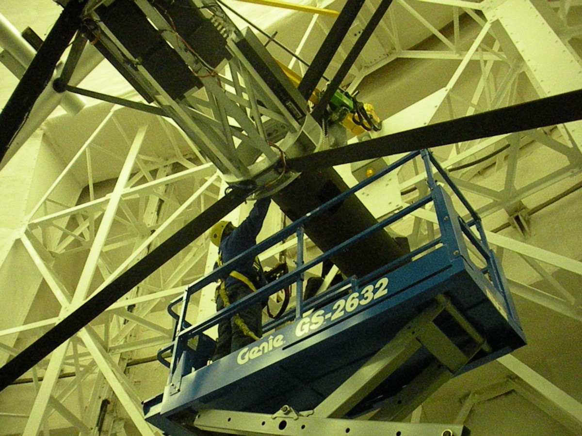
K Mirror (KM)Laser Launch Telescope (LLT)The GS Laser Launch Telescope (LLT) is a 450mm diameter aperture projector located in the shadow of the 1.0-meter diameter secondary mirror of the Gemini 8-meter telescope in order to provide on-axis launch of the five LGS constellation for MCAO operations. With an unvignettted field of view of +/-1.2arcmin and a 60:1 magnification ratio, the LLT enlarges the five, 5mm diameter gaussian laser beams overlapping on its entrance pupil, to a 300mm diameter footprint beam (these are diameters at the 1/e2 intensity points) on its 450mm diameter primary mirror. The LLT design consists of an unobstructed, afocal telescope using a diverging lens assembly followed by a fold mirror to expand the optical beam then direct it down towards an off-axis parabola (OAP) that provides collimated projection onto the sky. The opto-mechanical design includes a passive athermal focus mechanism that enables focusing. The LLT focus can be controlled remotely, which allows it to optimize the Laser spot size on the sky easily. Below it's an image of the LLT where it has been installed on the telescope.
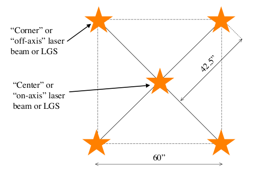
Laser ConstellationThe 5 beams are sent in a constellation with 4 LGS on the corner of a 60 arcsec square, plus one in the center. This constellation rotates on the sky to compensate for field rotation using the BTO K mirror (see K-mirror). The position of each LGS can be adjusted by a few arcseconds in the sky by using a combination of five tip-tilt platforms: the Fast Steering Array (FSA)
|
||||||||||||||||||

CANOPUSCanopus is the Adaptive Optics bench of GeMS . Below we described the characteristics of the main component of Canopus.
|
|||||||||||||||||||||||||||||||||||||||||
 Calibration Sources
 Deformable Mirrors
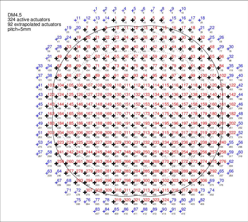
| DM0 | DM4.5 | DM9 | |
| Altitude (km) | 0 | 4.5 | 9 |
| Total actuators | 293 | 416 | 208 |
| Valid actuators | 240 | 324 | 120 |
| Slave actuators | 53 | 92 | 88 |
| Actuator coupling | 33% | 33% | 33% |
| Pitch | 5mm | 5mm | 10mm |
| Magnification | 7.9m -> 80mm | ||
| Layout | 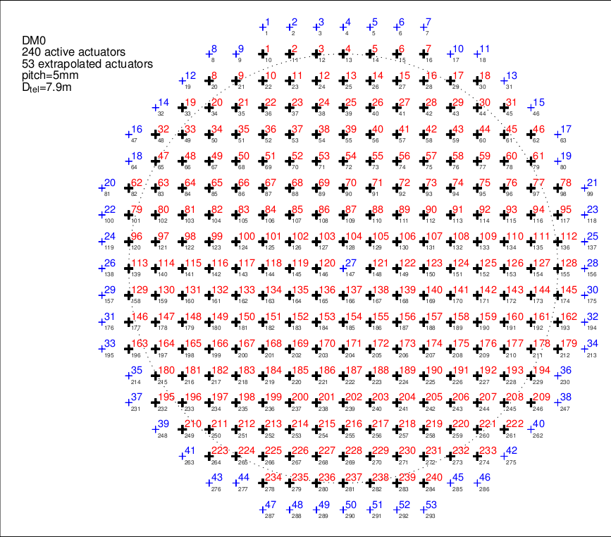 |
 |
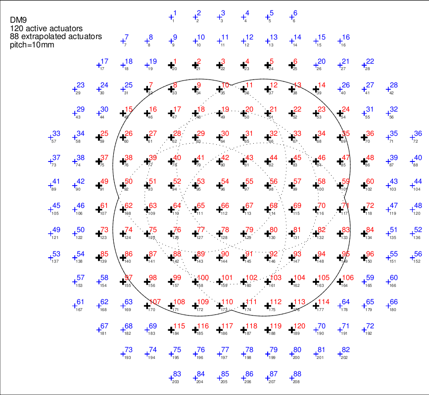 |
| Layout notes | In the layout plots above, black crosses, red numbers show valid actuators. Blue crosses, blue numbers show slave actuators. The dotted lines mark the various beams (for WFS 0 through 4). For the altitude DMs layout (DM4.5 and 9), the solid line marks the outer edge of the WFS beams, that is, it encloses the sensed part of the DM (dotted and solid lines computed for a LGS altitude of 90km, i.e. at zenith). | ||
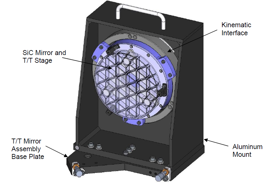
 Tip-Tilt Mirror
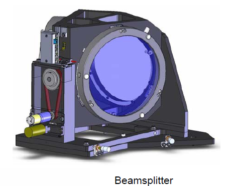
 Science Beam Splitter Assembly
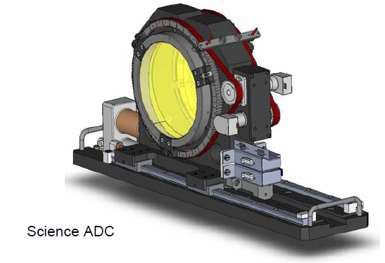
 Science Atmospheric Dispersion Compensator
 Output Focal
 Laser notch filter
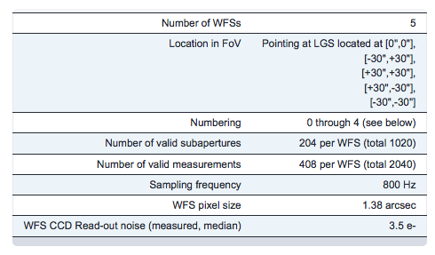
 LGSWFS
LGS WFS CCDs
LGS WFS Zoom
- Compensate for the range induced defocus; and while doing so
- Keep the wavefront aberrations small; and
- Keep the deformable mirror / lenslet registration error small.
 NGSWFS
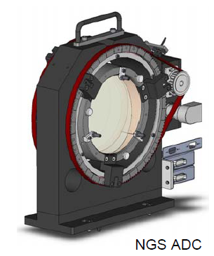
NGS ADC
TTWFS (Quadcells)
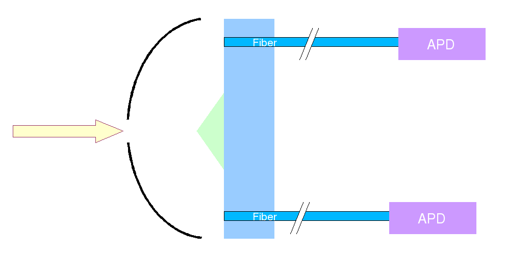
Slow Focus Sensor (SFS)
- Let's assume we start with everything in focus.
- The Sodium layer drifts by 200 meters up.
- This is seen by the LGS WFS.
- The system (DMs) compensate immediately for this defocus (normal close loop, using default control matrix).
- The NGS seen by the SFS will go out of focus (because this only corresponds to a sodium layer characteristics, and not a true defocus in the system, the NGS did not undergo any real defocus. However, it sees the defocus induced by the DM).
- The SFS will report a defocus.
- From this defocus, the system will drive the Zoom corrector.
- Because of the zoom corrector motion, the LGS WFS will see a defocus and will correct it.
- Assuming a proper calibration and sign, this will eventually converge and both the SFS and LGS WFS will be happy and with zero average focus.