Announcements
This section mainly describes how to prepare and check GSAOI observations at PhaseI/Phase II.
The easiest way to set up the observing sequences at Phase II is to use the Template Observations. The template observations are based on the examples in the OT Libraries and are filled in with the instrument resources selected in the Phase I proposal. Since the OT Library contains additional information including examples of different types of observations and some standard star information, we recommend to use the OT library in conjunction with the template observations. Note that library version may change from one semester to another. The best practice is to use (or at least review) the library version for the current observing semester. In this way, updates or changes to observation protocols will automatically be accounted for in new Phase II programs. Notes and descriptions appear directly in the library sequences to help observers understand how to best use the instruments.
Observing strategies
Given the complexity of the AO system, careful designing of GeMS/GSAOI observations is essential to achieve the desired performance required for the success of a science program. In this page we provide important information to guide the users with defining the observing strategies to follow with GeMS/GSAOI. The page also provides some guidelines to maximize observing efficiency and avoid some common errors. This information might be also useful to prepare a GeMS/GSAOI proposal submission (Phase I).
The users may want to take into account the following factors when designed observing sequences:
- Natural Guide stars (NGS)
- Recommended maximum exposure time for individual frames
- Read mode selection, co-adds and associated overheads
- Dithering and offset sizes
- Observing sky frames
Natural Guide stars (NGS)
As it is mentioned in Guiding Options page, the best and most uniform AO correction is achieved when the NGSs are positioned as close as possible to an equilateral triangle. The best asterisms are the ones that cover the larger portion of the field, and the more distant the stars are from each other, the lower the plate scale error will be. When the asterism is not the optimal or less than 3 NGS (2 or 1 NGS) are used, the users might expect larger variation in the delivered FHWM across the GSAOI FoV when compared to an optimal asterism selection, affecting the PSF uniformity across the field. If using only one NGS, the user can expect corrections slightly better compared to a single conjugate adaptive optics system (e.g. Altair). This is because the distribution of the 5 laser guide stars (LGS) on the sky (a 1' x 1' square) can better compensate the variation across the GSAOI FoV compared to a classical AO system with a single laser.
- The users should pay special attention to the guide star selection. By default the OT will automatically select the best asterism. Use the Automatic guide star selection mode to select the CWFS guide starrs and off-axis PWFS1 star.
- Sometimes the available optical catalogs, in particular UCAC4 and PPMX catalogs, show an inacurate R magnitude. If you have doubts about the magnitudes of the stars, always use the brighter stars available inside the Canopus patrol field. Rotating and shifting the GSAOI FoV may help with selecting a better asterism.
- Always assign the brightest guide star inside the Canopus patrol field to CWFS1 (default when the automatic guide star selection mode is used).
Recommended maximum exposure time for individual frames
For broad band filters (Z J H K Kp Ks), the maximum recommended exposure time for a single frame is 120 sec. Longer exposures are not recommended because the sky changes significantly between exposures, in particular in H, Kp, Ks and K bands, making proper sky subtraction difficult.
For narrow band filters, the maximum recommended exposure time is about 360 seconds. Make sure the exposures are long enough to be background limited. The users have to use the Faint Object or Very Faint Object read modes to observe with narrow band filters (see below).
Science programs that need separate sky frames should alternate the science observations with the sky frame observations. It is strongly recommended to observe a set of sky frames every 10 or 15 minutes (less is better), in particular for H and K filters (see below for details about sky frame observations).
Read mode selection, co-adds and associated overheads
The selection of the read mode and the number of co-adds used in any GeMS/GSAOI observation will directly impact in the overheads. It is important to balance between the read mode and the co-adds needed for your observation to minimize the associated overheads and optimize the S/N ratio of the resulting image. The overheads associated to each read mode are listed in this table. Note that in the Observing Tool GSAOI component, the read mode is automatically selected based on the filter and exposure time used. The user can select a different read mode using the OT GSAOI sequence iterator.
- If the observations are photon dominated, the Bright objects read mode may be used. If the objects in the field are too bright, then you can reduce the exposure time and add some co-adds to avoid saturation. However, the penalty will be the increase of the overheads due to the readout time associated to each co-add (see this table for details).
- The minimum exposure time with GSAOI using the Bright Object mode is 5.3sec.
- If the observations are background-limited, the Faint or Very faint object read modes may be used. The choice between the two read modes depends on the filters used and the exposure time of each frame. Note that the recommended exposure time per filters is automatically displayed in the GSAOI component. For broad band filters, it is recommended to use Faint Object read mode. For narrow band filters, it is recommended to use the Faint or Very Faint Object modes, depending on the exposure time. The readout noise can be reduced by using different read modes. For example, you can be tempted to observe with broad band filters and using the Very Faint Objects read mode to reduce as much as possible the read noise. The difference in read noise between Faint and Very Faint modes is ~3 e-. However, the penalty is an increase in the read out time by a factor of two, from 26.2 sec to 47.7 sec. Therefore, short exposure times (< 30 sec) with Very Faint Object read mode is not a very efficient combination.
Dithering and offset size
The GSAOI FOV is formed by four HAWAII-2RG 2k x 2k arrays mounted in a 2 x 2 mosaic. Note that due to the field distortion the arrays are not perfectly parallel to each other and the size of the gaps varies between 2.5" and 3.5" on the sky. Since most observations will require to dither in order to prevent any loss of information due to objects falling in the gaps, for the majority of the programs it is recommended that the dithering pattern is constructed with a minimum offset size of 4" between images.
When an observing sequence is constructed, the user has to keep in mind the following:
- Observe the same offset position multiple times is not recommended. There are some ''memory effects'' in the arrays when the same objects are observed multiple times at the same position (see section 3.4 in Schirmer et al. 2015 for details). Instead, a Random offset pattern, with a maximum offset of ~5" (or larger) is recommended.
- The CWFS NGSs must remain inside the patrol field area of Canopus in all steps defined in the GSAOI offset iterator. Note that in the case that one or more CWFS NGS move outside the Canopus patrol field area during dithering, an error message will be appear in the OT. A visual inspection of the offsets can be done using the OT Position Editor (see Visualization of Selected Asterism page for details).
- The off-axis PWFS1 star used for focus sensing must remain inside the ring between 5.8' and 6.95' in diameter from the Base Position. If the off-axis PWFS1 moves outside the ring during dithering, an error message will be appear in the OT.
- Remember, the overheads associated to dither, i.e. the time needed to open all loops, move the telescope and close all loops again, is 15 sec per dither position.
- Precise astrometry with GeMS: The complicated field distortion introduced by GeMS makes it difficult to obtain a good astrometric performance in a combined image when offsets are used. For programs that require a good astrometric accuracy, the primary recommendation is to not apply offsets between consecutive images. However, If the user needs to dither, then we suggest to use offsets no larger than 0.1- 0.2 arcsec (5 - 10 pixels). For detailed analysis of the astrometric performance with GeMS in crowded field, see B. Neichel et al. 2014, MNRAS, 445, 500 . For detailed information about GeMS commissioning an overall performance, see B. Neichel et al. 2014, MNRAS, 440, 1002.
Observing sky frames
As any near-IR imaging, GeMS/GSAOI observations require background subtraction. In the case of crowded fields, fields embedded in a large nebulosity or fields containing an extended object, sky frames have to be acquired using a blank region near the science target. In the case of sparse fields, the same science images can be used to create a master sky frame to subtract the background as long as enough dither positions are obtained to mask the objects in the individual frames.
A. General notes
When obtaining separate sky images, the dither pattern should be large enough to remove point sources in the combined sky frame (5"-10" is usually more than enough since the observations are unguided). Preferably, obtain the sky frames using the same exposure time and number of exposures as used for your science observations. Exposures shorter (or longer) than your science observations can make the sky subtraction (and your data reduction) more difficult. Avoid saturating objects in your sky frames when possible - remember, these frames are unguided, so feel free to move the center of the field around to exclude the brighter stars. Saturated objects are very difficult to remove and can affect the background subtraction. Observe sky frames every 10 - 15 minutes (less is better), particularly when using the H and K broad band filters.
B. Sparse fields
In the case of sparse fields, the science images can be used to construct a master sky frame to subtract the background. The offsets should be large enough to remove point sources and cover the gaps when making sky images. If the field contains sources that are more extended than point sources, it is recommend to construct a dither sequence with offsets slightly larger than the average size of these objects.
C. Crowded fields and fields with extended objects
For crowded fields, fields embedded in a large nebulosity or fields containing one or more extended object, sky frames have to be acquired in a blank region near the science target. In some cases (extended nebulosities, large star clusters) very large offsets are required to reach a blank field to observe the sky frame. If the offset to reach the sky frame is larger than 5 arcmin from the science position, the laser has to be shuttered and the science field will need to be re-acquired when the telescope is back from the sky, incurring in additional overheads to the program. Depending on the location of the blank field, the best observing strategy to follow is different.
C.1. Sky field located < 5 arcmin from the science target
- The sky frames can be interleaved with the science frames and included in the same observing sequence. Note that the entire sequence, including overheads, cannot be longer than 2.5 hours. A sequence longer than 2.5hrs requires an additional acquisition.
- If the science sequence includes more than one filter, the exposures are short and the sequence through all filters is not longer than 10 minutes (including overheads), then it is recommended first to observe the science target with all filters from blue to red, then move to the blank field and observe the sky frames in all filters in the reverse order. e.g. science (J) + science (H) + science (K) + sky (K) + sky (H) + sky (J). This strategy optimize the observations and minimize the overheads.
- If the science sequence includes more than one filter and the exposures are long, then it is recommended to observe one filter at time, e.g. science (J) + sky (J) + sky(H) + science (H) + science (K) + sky (K), within the same sequence. Note the use of the traditional ABBA pattern (science-sky-sky-science) in order to minimize offset overheads.
C.2. Sky field located > 5 arcmin from the science target
In this case, the laser propagation must be stopped due to Laser Clearing House restrictions. Therefore, when returning to science target, the LGSs have to be re-acquired and the CWFS NGS acquisition re-checked.
- For observations with only one filter, the best strategy is to create a sequence containing one science and a sequence containing one sky blocks, of a longer duration as scientifically useful (as noted above, it is recommended to obtain a sky block every 10 - 15 min or less of science). As many sequences as required to obtain the total time on-source should be provided. Note that it is not feasible to observe science-sky-sky-science in this case, since there can be a gap of more than 10min between the second sky block and the start of the second science block as the target (LGS+NGS) is re-acquired. Note that the sky observation must be defined in a separate sequence, and setup unguided.
- For sequences with short total time and multiple filter observations, the best strategy is to observe the science field in all filters and then move to the sky position. The sky observation must be defined in a separate sequence, and setup unguided.
- For long sequences with multiple filters observations, the best strategy is to observe the science field then move to sky for each filter. In this case, one science sequence and one sky sequence have to be created separately for each filter.
Overheads
For Phase I observing proposals, the information presented in this section can be used to estimate the overheads associated with a new science target. This information could be also useful for the Phase II planning of your observing programs. All of the values listed on this page are included in OT calculations of the execution time of an observation. However, only the actual overheads incurred at the time of the observation will be charged to the program.The detailed overhead information is presented below.
- Telescope and GeMS/GSAOI setup time
- Readout overheads
- Filter change overheads
- Dithering overheads
- Overheads associated to a sky sequence
1. Telescope and GeMS/GSAOI setup time
Acquisition overheads associated with setting up on each new science target include the time for slewing the telescope, launching the GeMS lasers, acquiring the GeMS laser and natural guide stars, closing all loops, and configuring the instrument. The table below gives the estimates for acquisition overheads.
| GeMS/GSAOI Acquisition Overheads | |
| Telescope Setup, Laser alignment, GSAOI configuration, NGS alignment and closing all loops | 30 minutes |
| Re-acquisition when the offset to the sky is larger than 5 arcmin from the target position | 10 minutes (1) |
(1) See Overheads associated to a sky sequence for details.
Applicants for GSAOI time should allow for one acquisition for approximately every 2.5 hours observed (including overheads).
The acquisition overheads listed above are based on average statistics from the last three GeMS/GSAOI commissioning runs and are included in OT calculations of the execution time of an observation.
2. Readout overheads
The table below lists the overheads associated with taking GSAOI images in the various read modes without telescope offsetting. These values include the time to read out the array Ncoadds times and to write the final FITS image.
| GSAOI overheads for each image | ||
| Read mode | Overheads | |
| Bright Objects | 21s + 5.6s * Ncoadds + 6.5s * (Ncoadds - 1) | |
| Faint Objects/Broad-band imaging | 21s + 22.4s * Ncoadds + 6.5s * (Ncoadds - 1) | |
| Very Faint Objects/Narrow-band images | 21s + 44.8s * Ncoadds + 6.5s * (Ncoadds - 1) | |
Filter change overhead
The overhead due to filter change without telescope offsetting is in average 15 sec (depend on the position of the filter in the wheel).
3. Dithering overheads
A normal GSAOI science observation sequence can include telescope offsets for image dithering and telescope offsets for sky background images. In both cases, some specific GeMS loops (Laser, NGS, etc) must either be paused or opened, and then resumed after the offsets. Note that the gaps between the four GSAOI arrays cause gaps in the imaging field. If continuous coverage of the field is needed, then multiple exposures have to be obtained at different dithering positions. A minimum dither step of 4 arcsec in the both X-direction and Y-direction (p and q-direction on the OT) is recommended. The overhead per dither step is 10 sec. This overhead is applicable when GeMS is working with 3 Canopus NGS stars.
4. Overheads associated to a sky sequence
The overheads associated to a sky sequence can be different depending on how large is the offset to the selected sky region.
- If the observation requires offsets to the sky shorter than 5 arcminutes from the base position, additional 30 seconds have to be accounted for the offset to the sky position. In this case, all NGS loops and dependencies are paused, and the probes are frozen (do not follow telescope offsets), but the LGS stabilization loop remain closed. Note that when the telescope is offsetting to the desired sky position, the same overhead per dither step on the sky (15 sec) is applicable.
- If the observation requires offsets to the sky larger than 5 arcminutes from the base position, the laser propagation must be stopped due to Laser Clearing House restrictions. Moreover, the laser has to be re-acquired and the NGS acquisition re-checked when the telescope moves back to the base position. In this case, additional 10 minutes have to be accounted for re-acquisition of the field. The sky sequence is observed un-guided and the overhead associated to telescope offsetting is 10 sec. Note that for this case, a separate GSAOI observation sequence will be required.
OT details
An introduction to the Gemini Observing Tool (OT) is presented elsewhere. This page provides detailed information on GSAOI component, GeMS component and GSAOI iterator.
- GSAOI Component
- GeMS AO Component
- Defining the CANOPUS AO WFS Stars and the off-axis PWFS1 Star
- GSAOI Sequence Iterator
- GSAOI Offset Iterator
GSAOI Component
The GSAOI component editor is accessed by selecting the GSAOI component in the science program, and is shown in the figure below:
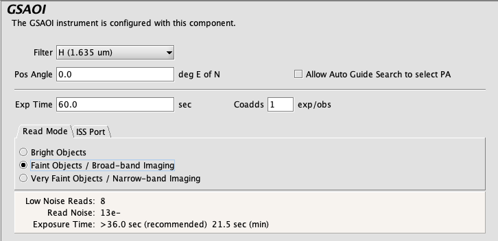
Selecting a filter
Choice of filter is made by clicking on the "Filter" pull down menu (i.e. the down-pointing arrows). The filter is chosen by selecting one from the list (by clicking on it). The central wavelength is given for each filter to assist with identification. You can move the vertical slider bar or click on the arrow buttons to browse the list.
Setting the position angle
The facility Cassegrain Rotator can rotate the instrument to any desired position angle (PA). Since the new GeMS guiding unit NGS2 uses configurable guiding windows (multi-region of interest), the automatic and manual search for the best asterism by the MASCOT algorithm using different PA is not longer an issue. Therefore, the "Allow Guide Search to select PA" checkbox in the "GSAOI Component" and in the "GeMS Guide Star Search" window (see Guide Star search algorithm below) are "uncheck" by default. Then, the MASCOT automated asterism-finding algorithm (see below) will pick the PA defined in the "Pos Angle" box (default PA is 0 degrees) to dermine the best asterism. The PA (in conventional astronomical notation of degrees east of north) can be set by typing in the "Pos Angle" box. The view of the science field in the position editor will reflect the selected angle. Alternatively the angle may be set or adjusted in the position editor itself by interactively rotating the science field.
Controlling the exposure
The exposure time is set by clicking in the relevant window and typing the required number of seconds. Each occurrence of the observe element will cause N exposures to be taken and coadded in the instrument control system. The value of N is set by typing an integer in the "coadds" window. The total exposure in each output image will be the exposure time multiplied by the number of coadds.
Arrays readout modes
The GSAOI arrays are read in three different modes for different kinds of observations. Select the button corresponding to the desired mode (Bright Objects, Faint Objects, or Very Faint Objects). Note that the low noise reads, the read noise, the recommended exposure time and the minimum exposure time will get updated when a different readmode is selected. Details about the read out modes can be found in the GSAOI Detector page.
GeMS AO Component
GSAOI can be used "only" with GeMS. The GeMs AO component is automatically included in the GSAOI observation element. The GeMS component editor is accessed by selecting the GeMS component in the science program.
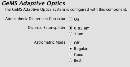
Observers should choose the default values for "Atmospheric Dispersion Corrector" (disable), for the Astrometric Mode ("Regular). The Dichroic beamsplitter is set to 0.85 µm and should not be changed.
Defining the CANOPUS AO WFS Stars and the off-axis PWFS1 Star
GeMS uses 1 to 3 Optical Natural Guide Stars to compensate for tip-tilt wave front sensing ( CANOPUS WFS or CWFS) and plate-scale modes variation. The slow focus information to compensate for sodium layer altitude variations is obtained using an off-axis Peripheral WFS 1 (PWFS1) star. The CWFS are specified in the target component of the main observation.

Information about the base position (i.e. the science object) and guide star(s) may be edited by clicking the appropriate line in the target table and then editing the various fields through the text boxes below. Changing the type of target may be done using the pull down menu at the middle left.
General information on how to add guide stars can be found on the guide star selection page. By default the OT will automatically select the best asterism that it can find, including the off-axis PWFS1 star for focus sensing, and place it in the Auto guide group. The Auto group cannot be edited. However, it can be copied into a editable Manual guide group using the Duplicate button ( ). Guide stars and off-axis PWFS1 star can also be added by clicking the green "plus" symbol in the target table. Manually-added guide stars and off-axis PWFS1 star or Manual guide groups can be deleted by clicking the red "cross" symbol in the table target. Double-click on a deactivated (greyed-out) guide group to activate it.
The figure below shows the selected CWFS stars (cyan squares with names) inside the Canopus Patrol field area (the red big circle) by the MASCOT algorithm. Other CWFS candidates within the magnitude interval defined by the observing conditions are also displayed (green circles). The off-axis PWFS1 star for focus sensing is automatically selected inside a ring between 5.8' and 6.95' in diameter from the Base Position (small green box and white arm inside the ring). The green and red circles inside the ring indicates the stars inside and outside the magnitude interval allowed by the defined observing conditions.

Use the automatically-selected guide group if possible. You may modify the PA if required (see above). Finer control of the automatic selection process and manual selection of guide stars using the Position Editor is provided by the GeMS Guide Star Search dialog describe below. You should only need to type in guide star details if the stars are not found in either the Gaia DR2 (default), UCAC4 or PPMXL catalogs.
In the figure below the GSAOI detector arrays are the large squares (cyan) and identified with a number. The GSAOI base position, defined in the target component, is marked as a small yellow cross within a circle. It is located at the bottom left corner of array 3, ~8.6" W and ~11.6" N from the center of the GSAOI detector arrays (~5" W and ~8" N from the lower left corner of array 3). The CANOPUS Wave Front Sensor (CWFS) patrol field area is represented by a large red circle with a radius of 1′, centered at the GSAOI base position and the center of NGS2 detector (large white square). Note that the red circle indicates the area where the CWFS can be selected. Up to three CWFS guide stars can be used for tip-tilt wave front sensing. Note also that the selection of an off-axis PWSF1 is mandatory.

Guide star search algorithm
As mentioned, CWFS guide stars are selected automatically. The asterism will update as the observation changes (e.g. position, offsets, conditions). Note that a change in the PA will not change the selected asterism. You may control some aspects of the selection algorithm or pick guide stars manually by clicking the "Manual GS" icon in the Position Editor (or using the buttons located in the target component if the Position Editor is not already open). The automated search for the guide stars is performed using the MASCOT (Multi-Conjugate Adaptive Optics Tool) algorithm. The algorithm searches diffferent catalogs for tip-tilt guide stars at given coordinates, compute the best tip-tilt guide star groups that will provide the best compensation (best Strehl) across the 2' in diameter CANOPUS field of view. The best asterism, based on the best average Strehl, is then selected by default. Note that in the automatic mode the selected stars cannot be removed.
In automatic mode the Gaia Data Release 2 (Gaia DR2) catalog is the default catalog for MASCOT. The bright and faint magnitude limits for the CWFS and the off-axis PWFS1 stars can be found in the Guiding Options page. For example, for IQ70/CC50/SBAny conditions, the bright and faint magnitude limits for CWFS are R=9.5 mag and R=18.0 mag, and the faint limits for the off-axis PWFS1 is R=16.45 mag, respectively.
In manual mode, the "GeMS Guide Star Search" window is displayed (upper panel in the figure below). The user can configure the catalog (default is "Gaia DR2" at ESA) by clicking on the "Catalog" pull down menu (i.e. the down-pointing arrow). By default, the "Allow position angle adjustments" checkbox is unchecked. The best asterims is found by using the PA defined in the "Pos Angle" inside the GSAOI Component (see above).

When a "Query" is requested, then a list of CWFS candidates inside the CANOPUS field of view is given in the table (lower panel in the figure below) and displayed in the Position Editor. The list can be reviewed and modified. Clicking on a line in the table will highlight the star in the Position Editor, and vice-versa (see the example below).

Guide stars can be selected manually by selecting one of the +CWFS buttons and then clicking on one of the marked stars. The information about that star will be copied to a Manual guide group in the target component. We recommend that you try the MASCOT selection first and then only do manual selections if MASCOT does not return acceptable results. Note that the off-axis PWFS1 star cannot be selected manually is this way.

By pressing on the "Analyze'" button (located at lower right of the GeMS Guide Star Search dialog) the MASCOT algorithm searches for the best asterisms and returns a list of candidates sorted by the average Strehl, the average rms and the maximum and minimum Strehl (see figure below). The algorithm can handle also sub-optimal cases. For example, it can return the best two-star asterism if a three-star asterism is not available.The user can also select more than one candidate asterism. When two or more asterisms are included in the target component, they are grouped separately. To add the candidate asterisms to the GSAOI Target Component, just press the "Add" button located at lower right in the figure below. Note that the selection of the off-axis PWFS1 for focus sensing is automatically added and the selected star is the same for all asterims candidates.

Visualization of the selected asterism and average Strehl
The selected asterism can be visualized in the position editor. In the figure below, the three CWFS stars are marked as a small green square. The average Strehl ratio, the associated error, the minimum and maximum Strehl values, calculated using the MASCOT algorithm, and the FWHM for the selected filter and Image Quality condition are shown at the bottom of the position editor. The Strehl map is visualized in the position editor as narrow curved green/yellow lines. To visualize the Strehl map, the average Strehl ratio, the associated error, the minimum and maximum Strehl values, and the FWHM, click on the "Strehl" button located in the left panel of the position editor.
The MASCOT algorithm returns an average Strehl ratio and the FWHM for the filter defined in the GSAOI Component and for the Image Quality selected in the Observing Conditions component. To estimate the average Strehl ratio and expected FWHM using different filters (e.g. J and H) and Image Quality conditions, the users have to change the filter in the GSAOI Component and the Image Quality in the Observing Conditions component. The calculation of the average "Strehl" ratio (and the visualization of the Strehl map) is performed automatically after a new filter and a new Image Quality condition are selected. Note the Image Quality Conditions allowed are IQ=20%-ile, IQ=70%-ile or IQ=85%-ile.
Important Note: The average Strehl, the associated error and the minimum and maximum Strehl delivered by the Mascot algorithm are only indicative. The values are based on data collected during the GeMS/GSAOI commissioning (see Table 1 in the GeMS performance web page). The FWHM values provided by the OT are also indicative and based on the values listed in Table in the GeMS performance web page. The Strehl calculation derived by the Mascot algorithm in the OT does not take into account for example the laser guide star (LGS) photon return (this parameter varies seasonally), turbulence profile (Cn2(h)), non-common path aberrations and other AO optimization and calibration parameters. The Strehl and FWHM values returned by the OT may vary if, for example, the LGS photon return is too low or turbulence profile is dominated by high altitude turbulence.

For choosing manually suitable CWFS guide stars and off-axis PWFS1 star consider the following:
- All observations must have from 1 to 3 CWFS guide stars for tip-tilt wave front sensing.
- All observations must have 1 off-axis PWFS1 star for focus sensing.
- The CWFS guide stars must have the limiting magnitudes given in the Guiding Opitons page.
- The difference in brightness between the three CWFS should not be larger than 3 mag.
Detailed information about the selection of GeMS guide stars and the restriction in magnitudes can be found in the GSAOI Guiding Options page.
GSAOI Iterator
The GSAOI Sequence Iterator is a member of a class of instrument iterators. Each works exactly the same way, except that different options are presented depending upon the instrument. The GSAOI iterators are required when the observation is stepping through different GSAOI components. Use this component to change the instrument configuration during the observation, for example, to repeat the same basic observation at two or more filters.
In right panel of the figure below we see a few iterator features (the left panel shows the GSAOI Science Observation).
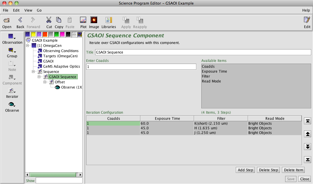
An iteration sequence ("GSAOI Sequence" in the above image) is set by choosing "GSAOI Sequence" from the "iterator" menu. The table columns in the "GSAOI Sequence Component" are items over which to iterate (four in total). In the example given below, we are iterating over filters. Table rows correspond to iterator steps. When an observing sequence is started, all the values in a row are set at once. Since there are three GSAOI configuration steps in this example, an offset iterator is required. It would be embedded inside the GSAOI sequence iterator (see below). Then, an "observe" element would produce an observe command for each of three filter setups times the number of offsets defined in the offset iterator, using the specified integration time defined in the main GSAOI component.
Rows or columns may be added and removed at will. Rows (iteration steps) may be rearranged using the arrow buttons. Rows can be added or removed by clicking "Add Step" or "Delete Step" buttons, and columns can be deleted by clicking "Delete Item". Adding column can be done by selecting one from the "Available Items" box.
In the above figure, the iteration the table shows the observations for one of the filters. The first twenty exposures are taken with the step 1 configuration (in this case the J filter) with the telescope dithering at each exposure (p, q offsets). Note that in the first 10 exposures the telescope is dithering on-source, with all guiding loops in "guide" mode. For the next 9 exposures, the telescope is dithering "on-sky" (for sky subtraction), with all guiding loops in "freeze" mode. After step 20, the instrument is re-configured with the H filter for the next 20 offset exposures (10 on-source and 10 on-sky).
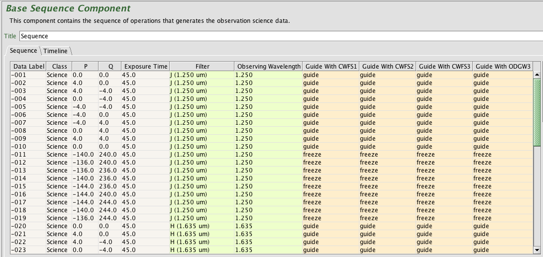
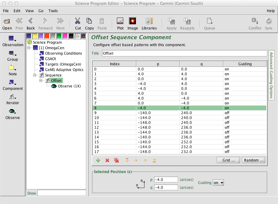
GSAOI Offset Iterator
The GSAOI Offset Iterator is a member of a offset iterator class. The offset iterator is common to all instruments and is used to define the sequence of dithers and sky offsets to be used. The offset sequence from the example given in the previous section is shown below. The offset sequence can be visualized using the position editor by clicking in the "offset" box at the Target menu. The different offset positions can be visualized in the position editor by selecting different steps in the figure below. This visualization is very useful to check if the selected guide stars are within the CANOPUS patrol field area and the GSAOI detectors during the observation. Detailed information on some of the considerations to be taken into account when setting up offset sequences with GSAOI can be found in the observing strategies page.
Phase II instructions
GSAOI Phase II Check list
- General
- It is strongly recommended to read the notes in the Observing Strategies page before you start to fill the phase II for your program. The page provides some guidelines to maximize observing efficiency and avoid some common errors.
- Have you selected appropriate templates from the GSAOI OT library? Have you gone through the checklist in the Top-level Program Overview note and included relevant standardized notes? Add notes with information about the program that will make it easier for the observer. Try to use the standardized notes provided in the OT Library.
- Have you read the details about the overhead calculations? Have you added a note explaining how many re-acquisitions you have assumed for the calculation of the overheads? Taking the correct overheads into account, do your defined observations fit within the allocated observing time?
- Have you checked the GSAOI Baseline Calibrations to see what is offered/required?
- If the PI requires calibrating standards beyond what is offered in the standard baseline calibrations, these must be defined, including a specific target, and time will be charged against the program for the observation.
- OT Setup
- In the GSAOI component, check that the best read mode has been selected for your science observation. Note that the minimum exposure times are defined by the read mode (see Detector Characteristics section)
- Are the integration times for your science observations reasonable? Are co-adds necessary? The recommended maximum exposure time for a single frame can be found here.
- Have you checked if the GSAOI observation sequences take no longer than 2.5 hours (including overheads)? If the observations of a particular target require several hours of on-source integration, be sure to create the necessary sequences to re-acquire the target?
- Have you checked if the sky background (which refers to optical sky background) in the Observing Conditions component has been set to "Any" (1 - 2.5 microns)?
- Have you checked if the water vapor in the Observing Conditions component has been set to "Any" (1 - 2.5 microns)?
- If there is a chance that any source will saturate the PI should include a note telling the observer what to do. Possible actions include: 1) nothing, 2) stop the observation and request feedback from the PI, 3) decrease the exposure time, 4) decrease the exposure time and increase the number of co-adds. Decreasing the exposure time may require changing the read mode, so the note should state whether these changes are allowed. Use the standardized notes provided in the OT Library.
- If the target will not be obvious the PI should include a finder chart or use the User (1) in the target component to identified the object. Add a note stating that centering is not important.
- If the observing sequence is non-standard the PI should include a note so that the observer is not caught off guard (and to prevent the observer from trying to "fix" the observation).
- Offset iterators should typically be located below sequence iterators (which change the instrument configuration) since the telescope offsets much more quickly than the instrument can reconfigure (e.g. change filters).
- Sky frames
- GeMS/GSAOI observations require background subtraction. In the case of sparse fields, the same science images can be used to create a master sky frame to subtract the background as long as enough dither positions are obtained to mask the objects in the individual frames. In the case of crowded fields, fields embedded in a large nebulosity or fields containing an extended object, sky frames have to be acquired using a blank region near the science target.
- Are sky frames included in the observing sequences? Do you have enough sky frames to properly subtract the sky? The sky may varied significantly in a short interval (2-5 minutes). This particularly true in H (1.65 microns) and K (2.2 microns) bands. Have you included enough sky frame observations to take into account for these variations in the sky?
- If the blank field for sky observations is located < 5 arcmin from the science target, the sky sequence should be included inside the same observing science sequence using a separate offset iterator (see examples in the OT library). If the blank field for sky observations is located > 5 arcmin from the science target, a separate sequence for the sky should be created. Detailed information about the different strategies to observe the sky can be found here.
- Guide stars
- Are CWFS (Canopus Wave Front Sensor) and the off-axis PWFS1 star for focus sensing selected for GSAOI? To choose the guide stars, use either the Auto GS (recommended) or Manual GS buttons in the OT position editor (see GeMS/GSAOI Guide Star selection page for details).
- Ensure that the CWFS and off-axis PWFS1 guide stars are not galaxies. Galaxies are not allowed as Guide Stars.
- The CWFS NGSs must remain inside the patrol field area of Canopus in all steps defined in the GSAOI offset iterator. The star used for focus sensing (off-axis PWFS1) must remain inside the area defined by the ring between 5.8' and 6.95' in diameter from the Base Position. In the case that the off-axis PWFS1 star moves outside the allowed area, an error message will be appear in the OT.
- The guide state in the offset iterator should be "guide" for all science dithers, and "freeze" for the sky dithers.